Battery Charger and Charge Level Indicator Circuits | 6 Different Circuit Build and Procedures
Making DIY circuits is always fun especially when you can make one using some cheap and gullible components. If you are looking for ideas to build battery chargers and charge level indicator circuits, then you’re exactly in the right place.
You can make a simple battery charger circuit using some common ICs. All you need is an LED light, battery, and a circuit, and you can make almost 6 types of amazing charge level indicators and automatic charging circuits.
Different types of battery chargers and charge level indicator circuits are demonstrated here. You’ll get to know about the followings topics in this article –
- Simple Battery Charger Circuit and Battery Level Indicator With Low Battery Recharge Alarm,
- Battery Charge Controller Circuit Using LM324 Comparator IC,
- LED Dot Display Based Battery Charge Level Indicator Circuit Diagram,
- 12v Battery Charger Circuit With Auto Cut Off,
- Simple Emergency Light Circuit with Automatic Charger,
- 12v Led Battery Level Indicator Circuit (Led Bar Graph).
These circuit schematics will definitely be helpful for your daily life battery charging applications. Besides, as a basic electronics learner, you’ll learn what a comparator is from below this article.
Simple Battery Charger Circuit and Battery Level Indicator With Low Battery Recharge Alarm
Here demonstrated a simple 12V rechargeable smart battery charger circuit. You can use this battery charger circuit for multiple purposes such as car battery chargers, Inverter battery chargers, Emergency light battery chargers, etc. You can learn to set an automatic indicator alarm circuit along this battery charger that will buzz when the battery needs a recharge.
Components required
Transformer (230V to 15V or 110V t0 15V)
Bridge rectifier (1N4007 x 4)
Capacitor (470µF, 50V)
Voltage regulator IC 7815
12V rechargeable battery
Diode (1N4148)
LED Zener diode 9V
Transistor (BC547 x 2)
Resistors (10kΩ, 1.5kΩ, 100kΩ Each ¼ Watt)
Buzzer (12V)
Working of battery charger circuit
The charging circuit is built around a voltage regulator IC 7815 and two transistors BC 548.
The main supply 230V or 110V is stepped down using a step-down transformer, and then it is rectified and filtered out.
Read: Full-wave bridge rectifier circuit with working explanation
That DC voltage is then fed to the voltage regulator IC 7815; the output will be regulated at 15V.
The 12-volt rechargeable battery is connected to the output of the voltage regulator, and it charges when the main power is available.
This circuit also indicates the charging status, that is the LED1 glows when the battery is charged (Above 10.5V).
When battery voltage goes below a particular value, LED1 stops glowing and the buzzer produces a sound indicating that the battery has been discharged.
Hope this guide has proven helpful for you to build your own battery charger circuit with the battery level indicator.
Battery Charge Controller Circuit Using LM324 Comparator IC
Generally, battery charge control circuits using 555 IC are often complex for many to comprehend. But a charge controller circuit using LM324 that is described below will definitely prove helpful to you as it automatically switches off the charger when the battery is full.
Although LM324 IC is used in this circuit, you can use any other comparator ICs like LM358, LM317, LM339, etc. Let’s learn in detail below.
Circuit Diagram of Charge Controller Circuit Using LM324
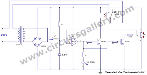
Components Required for Battery Charge Controller Circuit
- LM324 IC
- Zener diode 5.1V
- Bridge IC/1N4007X4
- Transistor BC548X2
- Led Green
- Capacitor 1000uF
- Resistor 1KX4, 100K
- Pot 50K/47K
- Relay 12V/10A
- Transformer 0-15V/2A
Here we have used LEDs to indicate the charging status. This charging controller circuit can be applied to any system that makes use of rechargeable batteries. Examples include emergency UPS, inverters, telephone receivers, etc.
Working Principle of Battery Charge Controller Circuit
- Step down transformer steps down the line voltage to 15 volts and the bridge rectifier does the AC to DC conversion process (rectification), it’s followed by the capacitor filter which removes AC ripples.
- The power supply for the working of the charger circuit is given from the battery (as it should always be monitoring the battery voltage level even when the mains supply is disconnected).
- The non-inverting terminal of the comparator is connected to a Zener diode and 1k resistor which are used to make a reference voltage of 5.1 volts, and its inverting terminal is used to monitor the battery level.
- The usage of a Zener diode instead of resistors makes sure that the reference value is independent of battery level and temperature variances.
- In fact, the comparison is not between the reference voltage and the actual battery voltage, but between a proportional value of battery level and the reference value. This proportional value is achieved by using a potentiometer.
- If the battery level is below the Lower Threshold Point (say LTP), then the reference voltage becomes higher than the proportional battery value. Thus, the output of the comparator becomes positive.
- Then the transistor is switched ON (as the output of the comparator is connected to the base of transistor BC548 through a 1k resistor) followed by the relay. I have used a freewheeling diode along with the relay to de-energize the inductor.
- And when the comparison goes reverse, the output of the comparator is low and transistors are OFF resulting in the disconnection of supply.
- The output of the comparator is also connected to another BC548 through a 1k resistor which makes hysteresis. That means when the charger is ON, the transistor is ON, and it makes a 100k resistor parallel with the respective voltage divider, then the drop across the divider will again decrease increasing the charging level.
- The Upper Threshold Point (voltage level when charger is switched OFF) can be set by varying the potentiometer.
- The difference between UTP and LTP (hysteresis) can be varied by changing the 100k resistor, decreasing the resistance increases the hysteresis and vice versa.
- An 8.2ohm 10-watt resistor connected in series with the circuit helps to limit the charging current. It’s not required for higher-capacity batteries as the charging time will increase.
As the threshold levels to turn ON and turn OFF the charger are different (hysteresis), it helps to avoid oscillation problems of the relay due to the leakage current of the battery. The threshold levels can be set by varying the potentiometer. While building the charge controller circuit using lm324, as we are switching the charger with the help of relays, you can connect any capacity battery.
High-current transformers are recommended when using higher-capacity batteries to decrease the charging time. For small-capacity batteries, you should use a series resistance to limit the charging current and that’s not necessary for higher-capacity batteries.
LED Dot Display Based Battery Charge Level Indicator Circuit Diagram
If you want to display the amount of battery charge, then you can follow various methods such as LED dot display, LED bar display, etc. Here, you can learn how to make a battery charge level indicator circuit using an LED dot display while keeping the LM3914 IC at the core.
You can also learn to make a temperature level sensor using the same IC (LM3914) below. The circuit that has been shown in this article is most suitable for a 12-volt battery. You can also build this circuit to display other voltages using the same method.
Circuit Diagram of 12 Volt Battery Status Indicator
Components Required for Battery Charge Level Indicator Circuit
- IC LM3914
- LED x 10
- Resistors (56kΩ, 18kΩ, 4.7kΩ)
- Potentiometer (10kΩ)
Working Procedure of the Battery Charge Level Indicator Circuit
- Here I used the LM3914 display driver IC to convert the battery voltage to indicate LEDs.
- It is basically a millivolt measuring IC which is able to convert a varying millivolt input into a corresponding LED indication like a linear analog display.
- The IC LM3914 can operate with a wide range of supply voltage (3V to 25V DC). We can control the brightness of LED by programming via an external resistor. The output pins of LM3914 are compatible with both TTL and CMOS.
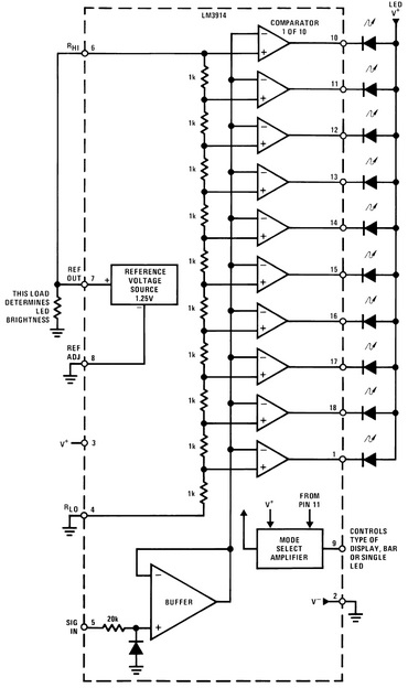
- We have connected the 4.7kΩ resistor between pins 6, 7, and ground. Thus, we can control the brightness of LEDs.
- 56 kΩ resistors and 10 kΩ potentiometers from a voltage divider network. In it, the potentiometer comes for the calibration of our display circuit.
- Our circuit comes with a design to monitor battery levels between 10.5V to 15V DC.
Calibration of Battery Charge Level Indicator Circuit
- Set up the circuit and connect a 12V DC supply to the input.
- Then adjust the 10KΩ potentiometer to see the 10th LED glow (in dot mode) or LEDs up to 10 glow (in bar mode).
- Now decrease the voltage in step by step up to 10.5 volts, then only LED1 will glow.
- To select dot mode or bar graph mode you will find a switch at the 9th pin. When you will switch it closed, pin 9 of the IC will get connected to the positive supply. Thus, the circuit will enable bar graph mode.
- Open the switch to enable dot display mode.
Other Usages of Dot Displayed Battery Level Circuit
- With slight alteration, the circuit can be used to monitor other voltage ranges.
- For this just eliminate the resistor R3 and connect the high voltage (less than 25V) to the input and adjust the potentiometer until the 10th LED glows (in dot mode).
- Now connect a low voltage at the input after removing the high voltage. Then connect a high-value potentiometer at the 4th pin, and adjust it until LED1 glows alone.
- Disconnect the potentiometer, and measure the resistance of the pot using a multimeter. Then connect a resistor in place of the potentiometer.
- That’s all; now your new voltage monitor is ready…!
LM3914 already has the design to operate in a battery charge level indicator circuit. You’ll just have to add the LEDs in the right positions or pins.
12v Battery Charger Circuit With Auto Cut Off
Here you can learn to build a simple DIY charge controller schematic that automatically turns ON the charger if the battery voltage is below the variable preset voltage (12 volts is chosen here) and automatically turns OFF the charger if the voltage reaches the variable preset voltage. Here the maximum charging is limited by a 13V Zener diode on the fifth terminal of 555 IC. You can set the preset voltage by adjusting the variable resistor. As the “555-timer” is used in this circuit, you must have an idea of the internal diagram of 555 to understand this 12-volt battery charge controller circuit. You can find the detailed demonstration below.
Automatic Battery Charger Circuit Diagram
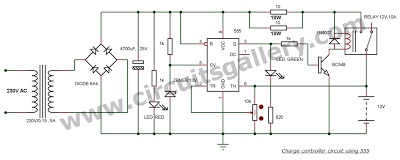
Automatic Battery Charger Circuit
Components Required for 12v Battery Charger Circuit
- IC 555
- Transistor BC 548
- Diode (6A4 x4 ,1N4007)
- Zener diode (13V)
- LED (red, green)
- Capacitor 4700uF,25V
- Resistor (1K x 3,820,5E 10W)
- Variable resistor 10K
- Relay 12V,10A
- Transformer 230V/0-15,5A
Components Pin Out
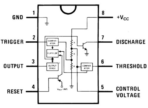
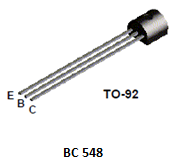
Working Procedure of Automatic 12v Battery Charger Circuit
- The positive terminal of the upper comparator of 555 is connected to 13V in order to turn OFF the charger if the battery charges above 13V.
- 13V is obtained by connecting a 13V Zener in series with a resistor.
- If the battery voltage is greater than 13V, the comparator output goes high and the flip-flop will be set. This turns OFF the transistor and the relay. For understanding relays, you must know how to connect relays and their working mechanism.
- If the battery voltage is below the preset voltage (set by us), the lower comparator will reset the flip-flop. This turns ON the transistor and the relay will switch to charge the battery.
- The recharge voltage (preset voltage) can be set by varying the variable resistor.
- Power ON is indicated by a red LED and charger ON status is indicated by a green LED.
Though 555 has taken control over most portions of the circuit, the Zener diode has been the most crucial component. To push this project to other levels of your work, you can use different values of Zener to meet your requirements.
Note: you can use op-amps to realize 12v Battery Charger Circuit too.
Simple Emergency Light Circuit with Automatic Charger
You can find the circuit diagram and working procedure of an emergency lighting circuit with a charge controller with automatic charging in this section. The given circuit is capable of turning on the light automatically when a power failure occurs and turning off if the main supply returns. This circuit also works as an automatic charge controller. Two LEDs are used as emergency light bulbs are used in this system. So, without any further ado, let’s see how you can make it.
Circuit Diagram of Automatic Emergency Light
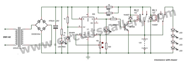
Components of Emergency Light Circuit with Automatic Charger
- IC 555
- Transistor BC 548
- Diode (6A4 x4, 1N4007x2)
- Zener diode (5.1V)
- LED (red, green, white)
- Capacitor 4700μF, 25V
- Resistor (1KΩ x 3, 820Ω, 5Ω 10W x 2)
- Variable resistor 10KΩ
- Relay (12V, 10Ax2)
- Transformer 230V/0-15,5A
Working Procedure of The Emergency Light Circuit
- The main component of this circuit is the 555 timer IC which controls the automatic charger circuit.
- Two 12V relays are used to switch the charger and emergency LED lights accordingly.
- Consider the main supply is on. The step-down transformer reduces the ac voltage level to 15V AC.
- The Bridge rectifier converts this to 15V DC and the 4700μF capacitor removes the ac ripples to make a flat DC.
- Green LED indicates the presence of main power. The 1KΩ resistor is used as a current-limiting resistor for LED.
- The relay connected to the LED is always ON. If the main power is present, the LEDs remain in the OFF state since they are connected to the NO (Normally Open) terminal of the Relay. You may need to read a bit about the connection diagram of the relay to know more about the Relay connection and configuration.
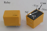
- The variable resistor is meant to set the voltage level for the charger activation, a 5.1V Zener diode is used to turn off the charger circuit if the battery voltage reaches at 13.8 volts which helps to Lead Acid battery’s long life.
- The negative terminal of the lower comparator is connected with the battery voltage to compare the battery voltage level below the pre-set level (pre-set level: voltage level to ON the charger can be set by varying the variable resistor).
- If the battery voltage reaches below the pre-set level, the lower comparator will reset the flip flop in the 555, which turns ON the charger.
- The battery is also connected to the positive terminal of the upper comparator. It checks if the battery voltage level is 13.8V. Then it sets the flip-flop and thus turns OFF the charger.
- At the time of power failure, all the charger circuits will be inactive and the relay RL2 connects the battery to LEDs. And thus it glows.
Components Pinout of Emergency Light and Automatic Charger Circuit

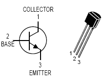
This circuit mainly focuses on lead-acid battery life. In this circuit design, we limit the maximum charging voltage to 13.8V as per the instructions from lead-acid battery manufacturers. In addition to that, we’ve deliberately chosen LED bulbs. LEDs provide long life since they draw very low currents. But take great care as the value of the current required depends on the number of LEDs connected in parallel.
12v Led Battery Level Indicator Circuit (Led Bar Graph)
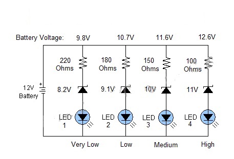
As lead-acid batteries require constant voltage charging, the inverters aren’t sufficient for your lead-acid batteries, and in that case, you may need a handmade battery voltage monitor circuit to maintain the 14 volts constant charging.
Though the LM324 IC is used in this circuit, you can still use an LM3914 IC to get 10 levels if you have enough budget for that. You can find your desired circuit design for the led level indicator monitor circuit that used Leds in levels of 8 with variable sensitivity in this section below.
Components Required
- LM 324 IC X 2
- LED X 8
- Resistor (1K X 17)
- Potentiometer(1K X2)
Battery monitor circuit diagram

Working of Voltage Detector
- Battery level comparison is done using LM324 IC which has 4 in-built comparators. Here we are using two ICs to get 8 levels.
- To each comparator’s inverting (negative) terminal, we are giving a reference voltage by using voltage divider resistors.
- Positive of all the comparators are shorted and connected to the positive terminal of the battery which is to be monitored.
- If the voltage of the battery is higher than the reference level of each comparator, then the output of the corresponding comparator will be high. Then the Led will glow.
- At the output, you can connect LED,s or barcode displays to increase good-looking.
- Here the LEDs glow in a bar graph display manner, if you want each Led’s to glow independently to indicate each level; you can connect a priority encoder IC 74147 and 74138 decoder IC.
- The sensitivity of this voltage tracker can be adjusted by varying the potentiometer.
- In case you want to control the charger circuit at a particular level, you can connect a relay at the output of the respective comparator. For this, you will have to use switching transistors.
This can easily be made using LM324 IC, and it will accurately give you real-time voltage level data of your circuit.
Conclusion
In this article, we’ve demonstrated how to build and briefly discussed how to build a 12v led battery level indicator in this article, we’ve demonstrated how to build your own automatic battery charger circuits, different types of battery level indicators, and battery charge level indicator LED circuits, and also briefly discussed how to build a 12v led battery level indicator circuit. Here we’ve used LM324 and LM3914 ICs, Zener diode, 555 timer circuits, and LED lights. Now, we hope you’ve found this guide helpful in building your very own battery charging circuits using some simple methods. If you have any confusion or questions regarding this topic, then don’t hesitate to ask in our comment section below.
- Simple Battery Charger Circuit and Battery Level Indicator With Low Battery Recharge Alarm
- Battery Charge Controller Circuit Using LM324 Comparator IC
- LED Dot Display Based Battery Charge Level Indicator Circuit Diagram
- 12v Battery Charger Circuit With Auto Cut Off
- Simple Emergency Light Circuit with Automatic Charger
- Conclusion
Subscribe to our newsletter
& plug into
the world of circuits