Ohm Resistance Chart | A Comprehensive Guide to Understanding Electrical Resistance
Ohm, the SI-derived unit is used to calculate a material’s or an electrical device’s electrical resistance. When a potential difference of one volt is supplied to a conductor, it has a resistance of one ohm, through which a current of one amp passes. Thus each ohm resistance is noted by different temperatures and a color code.

Ohm Resistance Chart
In both electrical and electronic circuits, resistors can be employed in a variety of ways to control the flow of current or to induce a voltage drop. However, the real resistor must possess some sort of “resistive” or “resistance” value in order to accomplish this. There are many different resistance levels for resistors, ranging from fractions of an Ohm (Ω) to millions of Ohms.
It would obviously be unfeasible to have resistors in every possible value, such as 1 ohm, 2 ohms, 3 ohms, 4 ohms, etc., as it would require literally tens of millions of individual resistors to cover all potential values. Instead, resistors are created in what is known as “preferred values”, which are the standard values of resistors.
Resistor Color Code
When the resistor’s body is large enough to see the print, like with large power resistors, the resistance value, tolerance, and wattage rating are typically printed onto the resistor as numbers or letters. The specs are noted in a color code when the resistor is small, such as a 1/4-watt carbon or film type, as the print would be difficult to see.
Practically all leaded resistors up to one watt in power are color-band labeled. The international standard IEC 60062 has a definition of coding. The marking codes for resistors and capacitors are described in this standard. The standard specifies the color bands as well as numerical codes, which are frequently used for surface mount SMD resistors.
These colored painted bands show both their resistive value and their tolerance with the resistor’s physical size to show its wattage rating. A method of identification created by these colored painted bands is often referred to as the Resistors Colour Code.
Resistor Color Code Chart
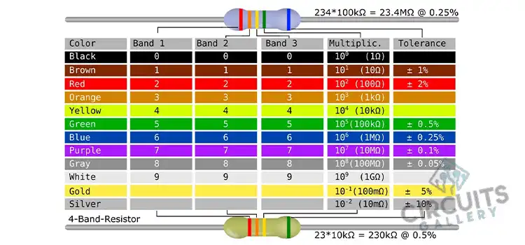
The chart below demonstrates how to calculate the resistance and tolerance for resistors. When the values are known, the table can also be used to specify the color of the bands. To quickly determine the resistor values, utilize an automatic resistor calculator.

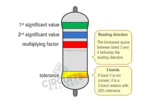
However, sometimes the reading direction may not be clear and the gap between the colors can also seem confusing. It is better to check the manufacturer’s documentation to be sure. If the color codes are burnt out or due to the timespan becoming hard to understand use an ohmmeter to determine the resistance.
4 Band Resistor
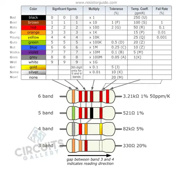
The most typical version is the four-band color code. Two bands for the resistance value, one for the multiplier, and one for the tolerance make up these resistors. For instance, if a resistor has four bands that are green, blue, red, and gold, one can use a color code table to determine that green denotes 5 and blue denotes 6.

The multiplier is represented by the third band, with red denoting a multiplier value of two (102). As a result, this resistor has a value of 56.102 = 56.100 = 5600 Ω. The resistor has a tolerance of 5%, as indicated by the gold band. Therefore, the resistance value ranges from 5320 Ω to 5880 Ω (5560 − 5%).
5 Band Resistor
High-precision resistors include an additional band to denote a third significant digit. The first three bands, therefore, reflect the significant numbers, the fourth band is the multiplication factor, and the fifth band is the tolerance.

For the instance, a resistor with a tolerance of 0.5% and the colors brown (1), yellow (4), violet (7), black (x 100 = x1), and green (0.5%). This five-band color scheme has certain exceptions. For instance, the extra band may occasionally denote a military specification for failure rate or a temperature coefficient (older or specialized resistors).
6 Band Resistor
Typically, high precision resistors with an additional band to define the temperature coefficient (ppm/C = ppm/K) have six bands of resistance. Brown (100 ppm/C) is the sixth band’s most prevalent color.

This means that the resistance value can fluctuate by 1000 ppm, or 0.1%, for a 10 °C change in temperature. Orange (3), red (2), brown (1), brown (x 10), green (1%), and red (50 ppm/°C) depict a 3.21 kΩ resistor with a 1% tolerance and a 50 ppm/°C temperature coefficient in the six band resistor example shown above.
Exceptions to the Color Code
Besides the standard version, there are some exceptions in the code that you have to know to know the accurate measurement. Here are the exceptions listed below.
Resistor with 5 bands and 4th band of gold or silver
An exception is five-band resistors, which are used on particular or vintage resistors and have a fourth band made of silver or gold. Significant digits are represented by the first two bands, a multiplication factor is represented by the third band, tolerance is represented by the fourth band, and temperature coefficient (ppm/K) is shown by the fifth band.
Deviating Colors
The gold and silver bands are frequently swapped out for a yellow and gray band in high-voltage resistors to keep metal and other foreign objects out of the coating.
Single Black Band or Zero-Ohm Resistor
A zero-ohm resistor is one with just one black band. In essence, it is a wire link that is packaged in the same physical package layout as a resistor and is used to connect traces on a printed circuit board (PCB). Due to its packing, the zero-ohm resistor can be installed on the circuit board using the same tools as conventional resistors.
Reliability Band
A reliability band is frequently present on resistors that are manufactured to military specifications. This range is reserved for the failure rate percentage per 1000 service hours.
Almost infrequently is this band used in industrial electronics. This dependability band is often used by four-band resistors. The US military manual MIL-HDBK-199 contains more details on this.
Calculation of Resistance Value
There are different online sites where you can find the resistor color code calculator. By just inserting the bands you can get the accurate result of the resistance value. However, you can do it yourself as well.
While calculating the resistor value using resistor color code calculators, the resistors are considered as n-band resistors where “n” represents the number of color bands printed on the resistor (n<=6). If it is a 6-band resistor, the bands can be named 1, 2, 3, 4, 5, and 6.

Here, the first significant number of resistor values is represented by band 1. Band 2 is the second important number. In both five-band and six-band resistors, band 3 can be seen as the third significant number. Then band 4 denotes a multiplier (decimal), band 5 displays the tolerance value as a percentage, and finally band 6 denotes the value of the temperature coefficient.
Surface Mount Resistors
Surface Mount Resistors, also known as SMD Resistors, are extremely tiny metal oxide film resistors with rectangular shapes that are intended to be soldered directly onto the surface of a circuit board, hence its name. The body of a surface mount resistor is typically made of ceramic, and a thick coating of metal oxide resistance is put there.
By changing the desired thickness, length, or kind of deposited film being utilized, the resistor’s resistance value may be regulated, and highly precise low tolerance resistors with tolerances as low as 0.1% can be created. They can also be soldered directly onto printed circuit boards thanks to the metal terminals or caps at either end of the body.
Conclusion
The resistive color code system has been extremely useful to enthusiasts due to its simplicity and ease of identification. It is important to know the calculation as much as knowing the code as without knowing it the ultimate goal of knowing the resistance value can be incomplete.
Hopefully, this article would help you to get a summary of information on resistors, resistor color codes, exceptions to resistor color codes, and a calculator for resistor color codes.
Subscribe to our newsletter
& plug into
the world of circuits