1-way vs 2-way vs 3-way Switch – What’s the Difference? | How do Switches Differ?
The key differences between these 3 switches are a lot more than that of the mentioned heading above. The contrasts exist based on construction, terminals, controlling location, and applications of these switches individually.
A one-way switch can be controlled from a single location, while a multiple-way switch can be controlled from multiple locations. Over years after its origination, nothing much has changed or upgraded in the working procedures of the switch.
Differences Between Switch Types 1-way, 2-way, and 3-way
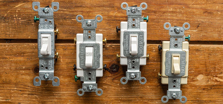
Single-way and multiple-way switches can be looked similar to each other through their switch covers post-installation. Different styles of switches are applied, but this sort of variation has nothing to do with the working principles and wiring of the switches.
1-way switch
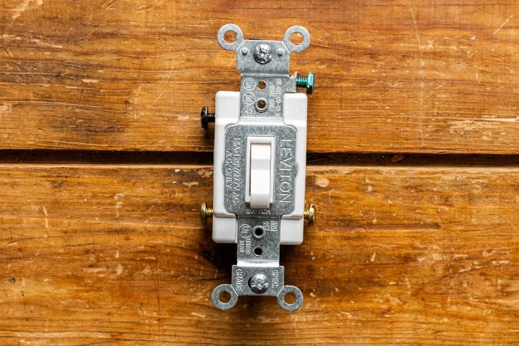
The 1-way switch is widely used worldwide for domestic purposes, especially in single cabins of the household. It is used to control the conduction of current from a certain definite location.
It follows the working mechanism of a single pole single throw (SPST) switch. The construction of a single-pole switch is the simplest of all, it only carries a ground connection and two metallic contacts.
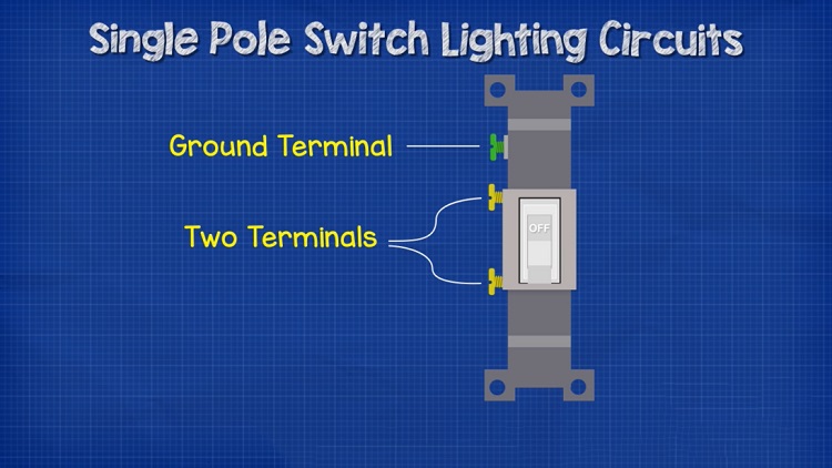
A track is kept between the two terminals, which is controlled by the outward toggle to complete the circuit connection or to break it.
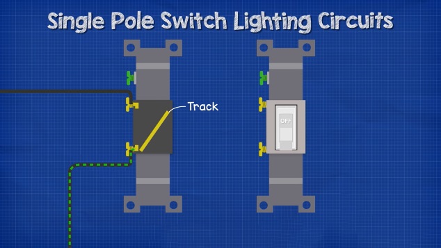
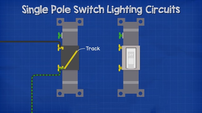
The current from the electrical source is conducted into one terminal, while the other brings out that current towards the rest of the circuit. This kind of switch works on the principle of make or break. Sometimes the ON/OFF label is tagged on the toggle of the one-way switch.
Pros of a 1-way switch
A one-way switch can be installed very easily without much effort. The installation cost is really low. The circuit wiring process is really simple for this specific switch.
Cons of a 1-way switch
On the other hand, this switch cannot be used for bigger rooms as the control of home electrical pieces of equipment using this switch can only be handled from a specific location. That’s why it is not generally used in large hall rooms or bigger manufacturing plants.
2-way switch
The 2-way switch is normally used to control the conduction of current from two different locations. It is specially used in stairway cases or long hallways, where the lights can be turned on and off from each of both ends. It is widely used for general industrial purposes as well. It follows the working mechanism of a single pole double throw switch.
A 2-way switch is two one-way switches merged into one. A 2-way switch has three terminals, one terminal is regarded as a common terminal. The others are called the L1 terminal and L2 terminal respectively. The switch carries another terminal which is the ground contact.
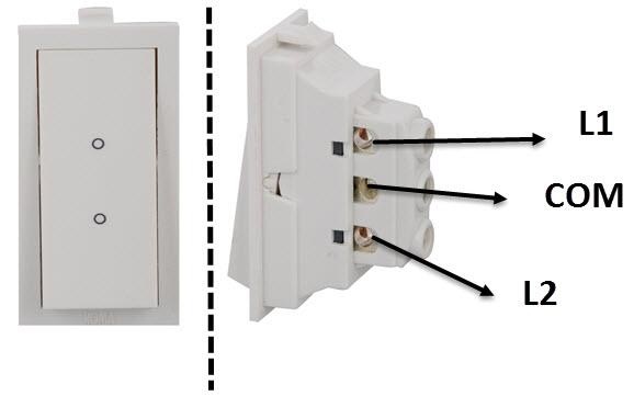
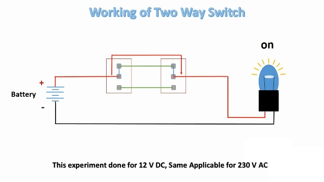
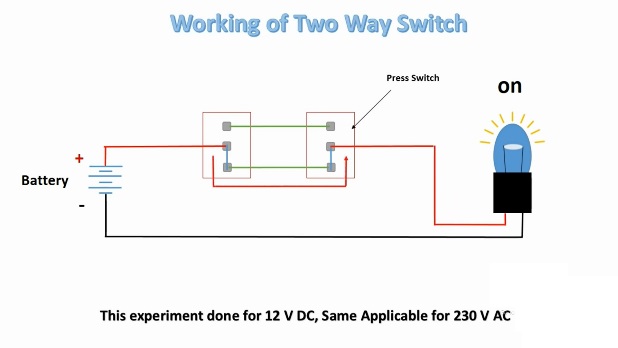
We typically use two 2-way switches in a circuit. The line of conduction is brought into the common terminals of both switches. A live wire is connected between the L1 terminals of both switches, the same is done for the L2 terminals as well. The track within the switch is altered by the toggle.
When both L1 switches are connected with the common terminal, a circuit is formed, thus the light is turned ON. The same goes for the L2 switches as well.
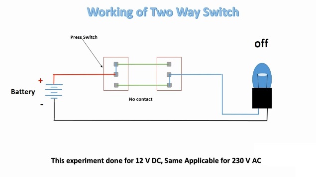
When one of the switches is toggled in the opposite direction of the other, the circuit conduction path becomes disrupted. Thus an open circuit is created and the light is turned OFF.

So, by using a two-way switch, we can control the devices connected to the circuit from both ends.
So we can say that the most significant advantage of a two-way switch is that it can be controlled from double locations. While walking up the stairs at night, we can turn on the stair light from the down-end switch, and then turn it off from the upper-end switch once we reach the top.
3-way switch
A three-way switch also follows the working mechanism of a single pole double throw switch. It is generally used in the larger hall-rooms to control the electrical devices such as fans, and lights from multiple locations. It carries four screw terminals- a common terminal, a couple of ground terminals, and a ground terminal that stays beneath of all.
Similar to two-way switches, the three-way switches are also used by couples in the circuit connection. The common terminal of one switch receives the incoming current from the source, while the end of the other switch delivers that current toward the device fixture.
Key Differences | 2-way vs. 3-way switch
Similar kind of screw terminals connects the switches through live wires. One major difference between the two-way and three-way switches is that there are no neutral wires connected between the three-way switches. While on the other hand, there are two neutral white wires connected between two 2-way switches.
It can be used for loads that are too sensitive to a continuous source of power. On the other hand, the installation process is more complicated than previous switches.
Comparison Table of Single Pole, Double Pole, and Triplet Pole Switch
Here’s a comparison table between 1-way (single-pole), 2-way (double-pole), and 3-way switches used in electrical circuits:
| Feature | 1-Way (Single-Pole) Switch | 2-Way (Double-Pole) Switch | 3-Way Switch |
| Number of Terminals | 2 (1 common, 1 traveler) | 4 (2 commons, 2 travelers) | 3 (1 common, 2 travelers) |
| On/Off Control | Single location control | Single location control | Two or more locations control |
| Wiring Configuration | Simple | Two options: DPST or DPDT | Complex (3-way setup) |
| Common Use | Controlling a 240V appliance with both lines, e.g., a water heater | Used for devices that require two separate on/off controls | Control lights from multiple locations |
| Example Applications | Turning a light on/off | Controlling a 240V appliance with both lines, e.g., water heater | Staircase lighting, hallway lighting, ceiling fans with multiple control points |
| Operation | Connect or disconnect the hot wire | Can connect/disconnect two hot wires simultaneously | Works in combination with another 3-way switch to control lighting from multiple locations |
| Wiring Complexity | Simple wiring with hot, neutral, and ground | More complex wiring, suitable for certain appliances | Requires a traveler wire between two 3-way switches |
| Locations of Use | Single-switch control in most rooms | Typically used for specific appliances or equipment | Multi-location control for lighting in larger areas |
| Convenience | Basic on/off control | Provides dual control for specific devices | Allows control of lights from multiple entry points |
How do You Differentiate a Single-way Switch from a 2-way Switch or a 3-way switch?
A single-way switch carries only two screw terminals. These two terminals connect the circuit from their ends and then work through the make-or-break mechanism. On the other hand, the two-way switch and three-way switch generally each have three screw terminals excluding the ground potential.
Conclusion
The terms one-way, two-way, or three-way signify the differences between the working principles and advantages of the switches. However, the basic principle of controlling the conduction of current through the circuit remains the priority for all of them.
Subscribe to our newsletter
& plug into
the world of circuits