Skip to content
Circuits Gallery
  • Home
  • BasicsExpand
    • Wiring
    • Op-Amp
    • Circuitry
    • Oscilloscope
    • Conductivity
    • Components
  • MicroControllerExpand
    • Arduino
    • PIC
    • Simulation
  • ProjectExpand
    • Using 555 Timer
  • DigitalExpand
    • Communication
  • Submit Project
Circuits Gallery
Home / Basics / Wiring / 10 Point Meter Pan Wiring Diagram | A Complete Guide

10 Point Meter Pan Wiring Diagram | A Complete Guide

A 10-point meter pan is a type of electrical panel used to measure and distribute power to a building or other structure. It usually has ten terminals that connect the incoming power lines, outgoing power lines, and the ground wire.

Typically, a 10-point meter pan contains the following wires:

  1. The electric company has three incoming power lines (L1, L2, and L3).
  2. T1, T2, and T3 are the three incoming electricity lines to the building or structure.
  3. 1 neutral (N) wire
  4. 1 G ground wire

These are the wires that need proper wiring to ensure that a 10-point meter pan is working properly. Now let’s get to know more about the wiring of it.

10 Point Meter Pan Wiring Diagram

How to Wire a 10-Point Meter Pan

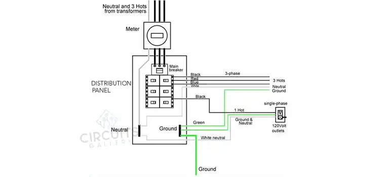
The following is the wiring diagram of a 10-point Meter Pan. 

10-Point Meter Pan Wiring Diagram

Figure 1: 10-Point Meter Pan Wiring Diagram

The instructions that you must follow to ensure successful wiring for a 10-point meter pan are given below:

  1. Connect the incoming electricity lines to the meter pan’s L1, L2, and L3 terminals.
  2. Connect the incoming electricity lines to the meter pan’s T1, T2, and T3 terminals.
  3. Connect the neutral wire to the meter pan’s N terminal.
  4. Connect the ground wire to the meter pan’s G terminal.

What Are the Safety Measurements That You Should Take While Wiring a 10-Point Meter Pan?

The safety measurements that you must always take while wiring a 10-point meter pan are:

  1. Before making any connections, always cut off the electricity to the meter pan.
  2. For all connections, use the appropriate wire gauge and insulation type.
  3. Check that all connections are snug and secure.
  4. Before resuming power, check the wiring to ensure everything is in good working order.

Do I Need to Obtain Permits for a Meter Pan Installation?

Yes, a permit is required to modify or install your meter pan. This ensures that the installation follows necessary processes to safeguard the safety of everyone in the building. Consider the worst-case situation, which no one wants.  

If an inexperienced electrician decides to take care of your wiring, the outcomes could be terrible for both your home and your health. Don’t make yourself a victim. Contact a licensed electrician.

How Does a Service Entrance Conductor Relate to the Meter Pan?

A service-entrance conductor is a wire that enters the service network. It connects the utility power to the meter pan and the service main disconnects. Understanding where the service begins and finishes is crucial in applying many code rules correctly.

Conclusion

If your meter pan has current transformers (CTs) or potential transformers (PTs), these must also be properly wired. Please seek the advice of an experienced electrician on this.

Table Of Contents
  1. How to Wire a 10-Point Meter Pan
  2. What Are the Safety Measurements That You Should Take While Wiring a 10-Point Meter Pan?
  3. Do I Need to Obtain Permits for a Meter Pan Installation?
  4. How Does a Service Entrance Conductor Relate to the Meter Pan?
  5. Conclusion

Subscribe to our newsletter

& plug into

the world of circuits

    A seasoned electronics enthusiast, Charles Clark is a key contributor to Circuits Gallery. From basic components to advanced microcontroller projects, Charles simplifies complex concepts with ease. His writings are a blend of expertise and passion, making electronics accessible to all. Whether it's circuitry or digital communication, Charles is the voice you can trust.

    Facebook Twitter Instagram

    Recent Blogs

    • How to Make A 75 To 300 Ohm Matching Transformer
      How to Make A 75 To 300 Ohm Matching Transformer? | A Step by Step Guide for You
    • How to Download Circuit Wizard? | Procedure for Downloading the Latest Version
    • What Gauge Wire from Battery to Starter
      What Gauge Wire from Battery to Starter? | Choosing the Right Wire Gauge
    • What Does 50 Milliamps Look Like on a Multimeter
      What Does 50 Milliamps Look Like on a Multimeter? | Let’s Find Out
    • How Many Watts Does a 32 Inch TV Use
      How Many Watts Does a 32 Inch TV Use? | Find Out the Required Wattage for Different Brands
    • What Size Conduit for 122 Wire
      What Size Conduit for 12/2 Wire? | Choosing the Right Conduit for Your 12/2 Wire

    Browse Categories

    • Arduino
    • Basics
    • Circuitry
    • Communication
    • Components
    • Conductivity
    • Digital
    • How To
    • MicroController
    • Op-Amp
    • Oscilloscope
    • PIC
    • Project
    • Simulation
    • Using 555 Timer
    • Wiring
    Circuits Gallery
    Join Our Community:

    Quick Links

    • About Us
    • Privacy Policy
    • Terms and Conditions
    • Submit Your Project
    • Contact Us

    Our Story

    Our journey designing innovative devices had immersed us in convoluted electronics. We realized mastery doesn't require elite degrees or industry secrets—just knowledge presented coherently. We became devoted to unraveling even quantum-complex circuits, diagram by diagram, so anyone eager to learn can unlock these secrets. By simplifying electronics fundamentals, we hope to ignite innovation in generations to come.

    © Copyright 2025 Circuits Gallery | All Rights Reserved.

    • Home
    • Basics
      • Wiring
      • Op-Amp
      • Circuitry
      • Oscilloscope
      • Conductivity
      • Components
    • MicroController
      • Arduino
      • PIC
      • Simulation
    • Project
      • Using 555 Timer
    • Digital
      • Communication
    • Submit Project
    Search