100 Amp Sub Panel Wiring Diagram [GUIDE AND EXPLANATION]
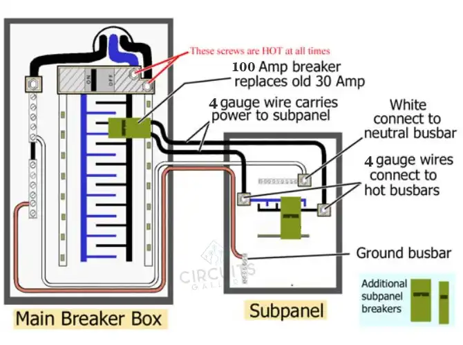
Typically, while wiring a subpanel, an electrician will first extend a feeder wire from the main panel to the subpanel. #4 copper wires or, more commonly, #2 aluminum wires are required for a 100-amp subpanel. The feeder breaker is then installed in the open double slot of the main service panel by the electrician.
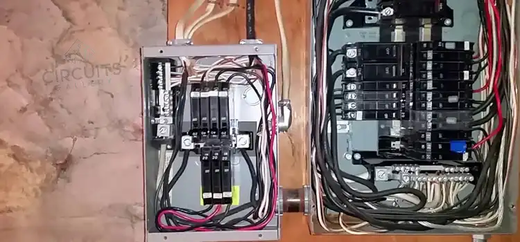
100 Amp Sub Panel Wiring Diagram
There are certain ways of 100 Amp Panel wiring which are explained below. However, it is always advisable to call an electrician to avoid any risk.
Sub Panel Connection
While installing a subpanel, an electrician generally first runs a feeder cable to the subpanel from the main panel. A three-wire cable with three insulated conductors and a bare copper ground wire is conventional. A 100-amp subpanel needs #4 copper wires or, more typically, #2 aluminum wires.
The electrician attaches the two hot wires from the feeder cable to the lugs on the hot bus bars in the subpanel, connects the neutral wire to the neutral bus bar, and the bare copper grounding wire to the grounding bus bar.
Connecting to the Main Panel
Next, the electrician connects the hot feeder wires to a new 240-volt circuit breaker at the main panel and then attaches the neutral and ground wires from the feeder cable to the respective bus bars in the main panel. Finally, the electrician installs the feeder breaker in the main service panel’s open double slot.
Consequently, separate circuit breakers for the additional circuits then become ready to be fitted in the subpanel.
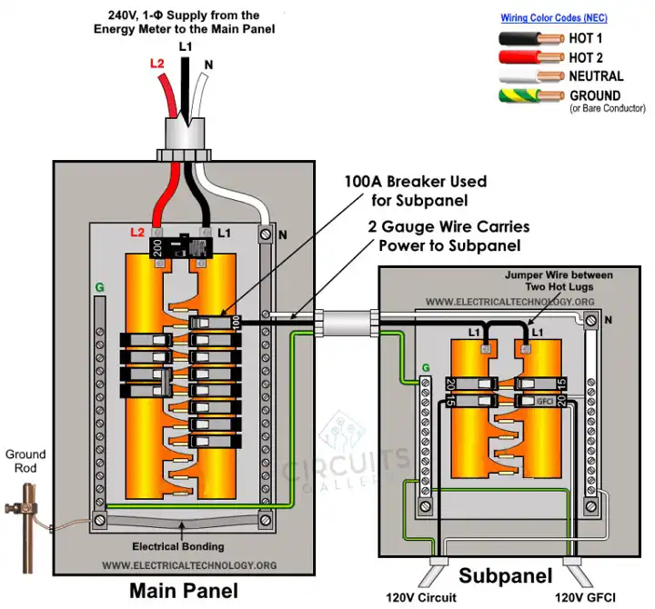
Wiring Installation of a 100A Subpanel for Only 120V
You will need all three wires, namely Hot 1 (Line 1 from the 1-Pole Breaker), Neutral from the Neutral busbar, and Ground from the ground terminal, as illustrated. To achieve just 120V supply voltage, you’ll need to use a jumper wire to connect Hot 1 (the black line) to both hot lugs in the subpanel. As a result, the single Hotwire is linked to both hot lugs, which fed up 120V load points.
To power up the load circuits through Hot, Neutral, and Gerund wire, both tiny circuit breakers and GFCI circuit breakers are linked in the diagram below.
Wiring a 100 Amp Circuit Breaker Box
Regardless of how confident you are with the job, wiring a 100-amp circuit breaker box might be a difficult undertaking that requires the approval of an electrician. It’s a potentially risky task that should only be attempted by an expert. Without an electrician’s guidance, you should only proceed as far as finding and opening the main breaker box.
Assessment
A 100-amp breaker box is typically used in a condo or two-bedroom apartment to put things in perspective. This voltage should supply enough power to run all of the major operations of a modest house without blowing any circuit breakers.
Moreover, larger residences, which typically have a breaker box of 200 amps or greater, may have a 100-amp subpanel installed.
Inspecting the Breaker Box
Prior to touching any wire, the electrician will inspect the breaker box that is already in place in the house. The 100-amp subpanel will be connected to this main breaker box. To connect a breaker sub panel, your main breaker must have two or more open slots.
However, if no slots are available, the electrician will have to rearrange some cables to make room.
Safety Precautions
There are some things you need to be careful of while conducting these types of electrical works.
- Before servicing, repairing, or installing electrical equipment, disconnect the power source (and double-check that it is indeed turned off). Turn off the main switch on the main consumer unit or distribution board to do this.
- While repairing or installing, never stand or touch damp or metal parts.
- Read all of the warnings and directions carefully before beginning this lesson or any other practical job involving electrical work.
- Always utilize the proper cable and wire sizes, as well as the appropriate outlets and switches, and circuit breakers. To determine the appropriate gauge size, you can use the Wire and Cable Size Calculator.
Can you feed a 100 amp sub panel with a 50 amp breaker?
The “100A” is the highest possible rating. Don’t go over 100 amps. You should, however, well surpass the 50A feed-breaker size. Even if 50A panels did exist, the number of slots available would be quite limited.
The Sum Up
In summary, when wiring a 100-amp subpanel, it’s vital to use the appropriate feeder wire, typically #4 copper or #2 aluminum, to ensure proper electrical capacity. For 120V supply voltage, a specific wiring configuration is necessary, utilizing jumper wires and circuit breakers. Wiring a 100-amp circuit breaker box is a complex task that should be left to experts, considering the potential risks involved. Before initiating any electrical work, safety precautions, including turning off the power source and using the correct wire sizes and components, must be strictly observed. It’s important to respect the panel’s ampacity, ensuring it doesn’t exceed 100 amps. Your safety remains paramount throughout the process, emphasizing adherence to safety guidelines and electrical standards. Cable
Subscribe to our newsletter
& plug into
the world of circuits