115/230 Volt Motor Wiring Diagram | A Comprehensive Guide
In the world of electrical engineering, understanding motor wiring diagrams is essential for professionals and enthusiasts alike. One common type of motor is the 115/230-volt motor, which is widely used in various applications. In this article, we will delve into the intricacies of wiring a 115/230-volt motor, providing you with the necessary information to ensure safe and efficient operation.
Wiring Diagram
Voltage is the electrical potential difference between two points, and it is measured in volts (V). In the case of a 115/230-volt motor, it means that the motor can operate on either 115 volts or 230 volts, depending on the wiring configuration. To wire a 115/230-volt motor, you will need a few basic tools and supplies. These include:
- A voltage tester
- A wire stripper
- Crimping tool
- Wire nuts
- Electrical tape
- A schematic diagram of the motor
Wiring a 115/230 Volt Motor for 115 Volt Operation:
- Disconnect the power to the motor.
- Locate the terminal block on the motor.
- Identify the following wires:
- L1: This is the hot wire.
- L2: This is the neutral wire.
- T1: This is the common wire.
- T2: This is the starting winding wire.
- Connect the L1 wire to the hot terminal on the motor.
- Connect the L2 wire to the neutral terminal on the motor.
- Connect the T1 wire to the common terminal on the motor.
- Connect the T2 wire to the starting winding terminal on the motor.
- Tape all connections securely.
- Turn on the power to the motor.
Wiring a 115/230 Volt Motor for 230 Volt Operation:
- Disconnect the power to the motor.
- Locate the terminal block on the motor.
- Identify the following wires:
- L1: This is the hot wire.
- L2: This is the neutral wire.
- T3: This is the common wire.
- T4: This is the starting winding wire.
- Connect the L1 wire to the hot terminal on the motor.
- Connect the L2 wire to the neutral terminal on the motor.
- Connect the T3 wire to the common terminal on the motor.
- Connect the T4 wire to the starting winding terminal on the motor.
- Tape all connections securely.
- Turn on the power to the motor.
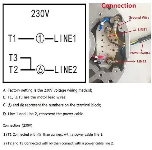
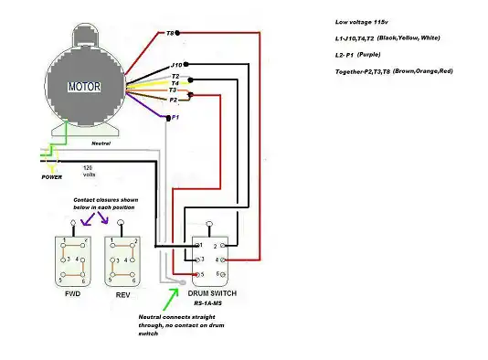
Figure: Schematic Diagram of a 115/230 Volt Motor
Instructions to Properly Wire Them
To properly wire a 115/230-volt motor, you need to follow the specific guidelines outlined in the motor’s documentation. However, we can provide a general wiring diagram that will give you a good starting point.
- Determine the Motor’s Voltage Requirement: Before proceeding with the wiring, verify the motor’s voltage requirement. Most 115/230-volt motors have a dual voltage rating, allowing them to operate on either 115 volts or 230 volts. This information can usually be found on the motor’s nameplate or in the manufacturer’s documentation.
- Select the Voltage Configuration: Once you have determined the motor’s voltage requirement, you need to select the appropriate voltage configuration. This can usually be done by changing the position of specific wires or jumpers inside the motor’s terminal box.
- Wiring Configuration for 115 Volts: If you intend to operate the motor on 115 volts, the wiring configuration will differ from the 230-volt setup. Typically, the motor will have different terminals labeled for 115-volt operation. Follow the manufacturer’s instructions to connect the appropriate wires to these terminals.
- Wiring Configuration for 230 Volts: For 230-volt operation, the wiring configuration will be different from the 115-volt setup. The motor will have separate terminals labeled for 230-volt operation. Again, make sure to follow the manufacturer’s instructions to connect the correct wires to these terminals.
- Grounding: Proper grounding is crucial for the safe operation of any electrical equipment. Ensure that the motor’s grounding conductor is connected to a suitable grounding point, such as a grounding screw or a grounding bus bar.
Safety Precautions
When working with electrical components, it is vital to prioritize safety. Here are some safety precautions to keep in mind while wiring a 115/230-volt motor:
- Always disconnect the power supply before working on the motor.
- Use appropriate personal protective equipment, such as insulated gloves and safety goggles.
- Follow the manufacturer’s instructions and guidelines precisely.
- Double-check all connections before applying power to the motor.
- If you are unsure or uncomfortable with the wiring process, seek assistance from a qualified electrician.
Frequently Asked Questions
Is it necessary to turn off the power when wiring the motor?
Absolutely. Safety is paramount. Always disconnect power before working on electrical systems to prevent the risk of electrical shock or injury.
Can I extend the motor’s ground wire if it’s too short?
It’s not recommended. Instead, use approved connectors or junction boxes to extend wiring safely. Altering the motor’s original ground wire may compromise safety.
Do I need a professional electrician for wiring my motor?
While the wiring process is straightforward, if you’re unsure or uncomfortable with electrical work, it’s advisable to consult a professional electrician to ensure safety and compliance with local regulations.
To Conclude
Understanding the wiring diagram for a 115/230-volt motor is essential for anyone working with electrical systems. By following the manufacturer’s instructions and taking the necessary safety precautions, you can ensure the proper installation and operation of the motor. Remember, when it comes to electrical work, safety should always be the top priority.
Subscribe to our newsletter
& plug into
the world of circuits