208v Photocell Wiring Diagram | Explained with Step-By-Step Instructions
Photocells are often used to switch lights on when it gets dark and off when it gets light outdoors. A diagram that shows how to wire a photocell (a photoresistor or light sensor) into an electrical circuit is known as a photocell wiring diagram. This is used to regulate lights based on light levels in the environment.
A 208V photocell wiring diagram is drawn by connecting a photocell to control lighting in a circuit that operates at 208 volts. In this article, we will discuss in detail about 208V photocell wiring diagram and how to draw it.
Entrails of A 208V Photocell Wiring Diagram
A proper wiring diagram can be made if you have the proper tools and knowledge. From safety to planning to wiring everything has to be done cautiously. Here are the required materials and instructions to draw a 208V photocell wiring diagram.
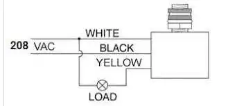
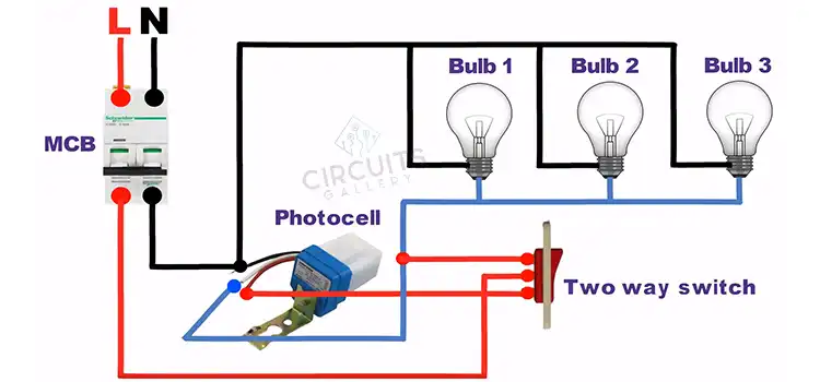
Figure 1: A simple 208V photocell circuit
Required Materials and Tools
- Photocell or Photoresistor
- Lighting Fixture or Load
- 208V Power Source
Different Connections of 208V Photocell Wiring Diagram
Before working on any electrical wiring, the power supply should be turned off at the circuit breaker or disconnected. Here are some steps you may follow to make a 208V photocell wiring diagram.
- Photocell Connection
- Connect one wire from the photocell to one of the hot wires from the power source. This wire is normally black.
- Connect the other wire from the photocell to the hot wire, usually red, of the lighting fixture.
- Neutral Connection
- Connect the neutral wire from the lighting fixture to the neutral wire from the power source. The neutral wire is usually white.
- Ground Connection
- Connect the ground wire from the lighting fixture to the ground wire from the 208V power source. The wire is usually green or bare.
- Second Hot Wire Connection
- In a 208V circuit, there are two hot wires. Connect the lighting fixture’s second hot wire from the power source directly to the hot wire. Generally, both of the wires are red.
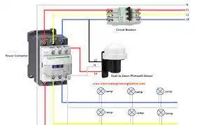
Figure 2: Photocell Wiring Diagram
Safety Regarding a 208V Photocell Wiring Diagram
There are some important safety regards for a wiring diagram. Here are some important rules that should be followed:
- Proper knowledge and training are required to work with electrical systems.
- Turn off the power to the circuit at the source before drawing the diagram or working on any electrical component.
- Use lockout procedures to prevent the circuit from accidentally being energized. To measure voltage accurately, you should use a voltage multimeter. to confirm that.
- Ensure you have the correct tools and equipment for the task, including insulated screwdrivers and pliers designed for electrical work.
- Keep a record of your wiring diagram and any modifications made to the electrical system.
Frequently Asked Questions and Answers – FAQs
Q1. How Many Wires for 208V?
A 208-volt single-phase system typically has two hot wires. To have a 208-volt single-phase circuit, 2 hot wires from a 2 pole breaker are needed. Each hot wire is 120 volts to the ground and 208 volts between the hot wires, and then you need an equipment grounding conductor.
Q2. What Colors are Used for 208V 3-Phase Wiring?
Wires used for 208 V AC three-phase wiring are:
- Black = Hot 1 or Line 1.
- Red = Hot 2 or Line 2.
- Blue = Hot 3 or Line 3.
- White = Neutral Wire.
- Green = Bare Conductor as Ground wire.
Q3. What is a Photocell?
A photocell is a resistor that changes resistance depending on the amount of light incident on it. The energy of photons hitting the semiconductor frees electrons to flow, decreasing the resistance. It is usually used to detect and respond to light levels in various applications.
Conclusion
With the proper tools and knowledge, a 208V photocell wiring diagram can be drawn. However, doing any electrical work has a lot of potential risks. Therefore, proper caution and safety measures should be followed and it’s best to seek the assistance of a qualified electrician or engineer to ensure safety and integrity.
Subscribe to our newsletter
& plug into
the world of circuits