24V Electric Scooter Controller Wiring Diagram | Learn Ins and Outs of the Wiring!
Electric scooters provide an efficient and environmentally friendly way to commute short distances. At the heart of an electric scooter is the controller, which regulates power from the battery to the motor. Properly wiring the 24V electric scooter controller is crucial for safe operation and optimum performance.
This guide will provide a comprehensive 24V electric scooter controller wiring diagram along with step-by-step instructions to connect all the components. We will also cover safety precautions, required tools, testing procedures, and troubleshooting tips. Let’s dive in!
24V Electric Scooter Controller Wiring Diagram
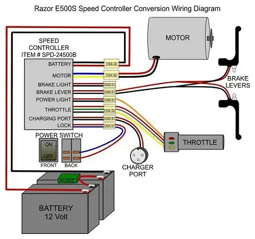
The following wiring diagram shows the basic connections for a 24V electric scooter controller:
Terminal Identification
- B+: Positive battery terminal
- B-: Negative battery terminal
- M+: Positive motor terminal
- M-: Negative motor terminal
- T: Throttle signal wire
- P: Brake signal wire
- H: Hall sensor wires (3 wires, typically red, yellow, and blue)
- L: Key switch wire
- D: Display wire (optional)
Wiring Connection of the Scooter Controller
Here are brief descriptions of how each component connects to the 24V electric scooter controller:
Battery: The positive and negative terminals connect to the controller’s B+ and B- inputs. Provides power to the system.
Controller: Central component that connects to all electrical systems. Regulates power to the motor and accessories.
Motor: Positive and negative motor wires connect to the controller’s M+ and M- outputs.
Throttle: The throttle cable connects to the T input on the controller, allowing variable speed control.
Brake Levers: The brake cable attaches to the P input on the controller to activate braking.
Power Switch: Wired in line with the battery positive to turn the electrical system on and off.
Charger Port: Provides connection point for battery charger to recharge the battery.
Lock: Some locks have an integrated switch that disables the controller when locked.
Headlight: Positive and negative headlight wires connect to the lighting output on the controller.
Tail light: Tail Light wires also attach to lighting outputs on the controller.
Horn: Horn wires connect to the horn output on the controller.
Safety Precautions You will Need to Follow
Working with electrical components can be hazardous if safety is not taken seriously. Here are some guidelines when wiring a 24V electric scooter controller:
- Disconnect the battery when wiring to avoid shocks or shorts.
- Insulate all connections with heat shrink tubing or electrical tape.
- Use proper wire gauges rated for the electric current draw.
- Follow local electrical codes and safety standards.
- Double-check all connections before turning on.
- Wear eye protection when soldering or handling batteries.
- Ensure cables are secured so they won’t get damaged.
- Use caution when probing circuits with a multimeter.
Following safety procedures is crucial when dealing with high-voltage electricity to avoid injury or damage.
Step-by-Step Wiring Procedure for 24V Electric Scooter Controller
Follow these steps to connect all the components to the 24V controller:
1. Disconnect the Battery
First and most importantly, disconnect the battery by removing the fuse or disconnecting the positive terminal. This isolates the electrical system and allows safe wiring.
2. Mount the Controller
Secure the controller in a protected area using the mounting tabs and hardware. Make sure to orient it so the wiring terminals are easily accessible.
3. Wire the Battery Connection
- Connect the positive (red) battery cable to the B+ terminal on the controller.
- Connect the negative (black) battery cable to the B- B-terminal.
4. Connect the Motor Wires
- Wire the positive (typically red) motor wire to the M+ terminal on the controller.
- The negative (black) motor wire goes to the M- M-terminal.
5. Install the Throttle Wire
- The throttle has a thin signal wire that needs to reach the T terminal on the controller.
- For twist throttles, secure the throttle assembly in an ergonomic spot on the handlebars.
6. Connect the Brake Lever
- There will be a brake wire leading from the brake levers that gets wired to the P terminal.
- Make sure to install quality brake levers in an easily accessible position.
7. Wire Accessory Components (Optional)
- Wire lights, horns, displays, or other accessories to wiring blocks on the controller if equipped.
- Refer to the controller and component manuals for specifics.
8. Connect the Power Switch
- The power switch taps into the main battery positive wire.
- This cuts all power when in the off position.
- Mount it near the throttle for easy access.
9. Check Wiring
- Verify correct wiring against the diagram.
- Ensure solid, tight connections.
- Confirm wires are secured and protected.
Double-checking all wiring at this stage helps avoid issues down the line.
Testing and Troubleshooting
Before riding the scooter, it’s important to test the electrics and troubleshoot any issues:
- Power-Up Test: Turn on the scooter without sitting on it. The wheel should not spin. If it does, recheck the wiring against the diagram.
- Operational Test: Sit on the scooter, turn it on, and operate the throttle. The motor should respond smoothly. Test braking as well.
- Check Voltage: Use a multimeter to verify the voltage of the battery and components. Voltage should be around 24V.
- Inspect Wiring: Look for frayed wires, damaged insulation, loose terminals, or loose connectors that may cause problems.
- Diagnose Issues: If the motor or components are unresponsive, methodically check continuity in the circuits and components. Isolate and repair the faulty wiring.
Thorough testing and inspection of all wiring and components help identify and prevent problems down the road.
Maintenance Tips
Proper maintenance will keep your electric scooter’s wiring in good condition for years:
- Periodically inspect wires and connections for damage.
- Check terminals and connectors for looseness and tighten as needed.
- Look for corrosion on terminals and clean as required.
- Confirm wires have slack and avoid pulling taut when steering.
- Use dielectric grease on connections to prevent corrosion.
- Replace damaged components like worn cables or wires.
Well-maintained wiring prevents many common issues with electric scooter electrics.
Frequently Asked Questions (FAQs)
1. How to Determine the Correct Wire Size for Electric Scooter?
Answer: If a single-phase motor hums but fails to start, a bad capacitor is often the cause. Replace the run capacitor with one of the proper capacitance values for the motor according to the wiring diagram.
2. Where Is the Best Place to Mount the Scooter Controller?
Answer: Mount the controller in a protected area like under the seat or in the leg shield. Ensure it is secured and oriented so the wiring terminals are easily accessible for connections.
3. Motor running but the Throttle Is Unresponsive. What to do?
Answer: If the motor runs continuously at full speed regardless of throttle position, it likely indicates a wiring issue with the throttle or controller. Check that the throttle wire is securely connected to the T terminal on the controller.
To Conclude
Understanding the wiring diagram and connections is essential for constructing an electric scooter with a fully functional 24V controller system. Follow the safety guidelines outlined and take time to carefully complete each wiring step.
With quality components and good wiring practices, your electric scooter will provide miles of reliable service. So, check those connections against the diagram and enjoy the ride!
- 24V Electric Scooter Controller Wiring Diagram
- Terminal Identification
- Wiring Connection of the Scooter Controller
- Safety Precautions You will Need to Follow
- Step-by-Step Wiring Procedure for 24V Electric Scooter Controller
- Testing and Troubleshooting
- Maintenance Tips
- Frequently Asked Questions (FAQs)
- To Conclude
Subscribe to our newsletter
& plug into
the world of circuits