277v Light Switch Wiring Diagram | Explained with Step-By-Step Instructions
A switch wiring diagram is a visual representation that shows how electrical components, particularly switches, are connected within an electrical circuit. A 277v light switch wiring diagram shows how light switches are connected and operated in 277 Volts.
It provides a clear and detailed view of the wiring configuration, helping electricians and individuals to understand how to properly wire a switch and control the flow of electricity in a circuit. In this article, we will discuss in detail the 277v light switch wiring diagram and how to draw it.
How to Draw a 277v Light Switch Wiring Diagram?
A proper light switch diagram can be made if you have the proper tools and knowledge. From safety to planning to wiring everything has to be done cautiously. Here are the required materials and instructions to draw a 277v Light Wiring Diagram.
Required Materials and Tools
- 277V Power Supply
- Light Fixture
- 277V Light Switch
- Electrical Wire (THHN or similar)
- Wire Nuts
- Screwdrivers
- Wire Strippers
- Electrical Box (if applicable)
- Circuit Breaker
Instructions
Before working on any electrical wiring, the power supply should be turned off at the circuit breaker or disconnected. Here are some steps you may follow to make a 277v light switch wiring system:
- Wiring Planning: The location of the light fixture and light switch should be determined first. Plan the routing of the electrical wires, making sure they are properly supported and protected in conduit or cable sheathing.
- Install the Light Fixture: Following the manufacturer’s instructions, mount the light fixture at the desired location. Usually, this involves attaching it to a ceiling or wall.
- Install the Light Switch:
To install the standard 277V light switch, follow these general steps:
- Cut a hole in the wall where you want to install the switch box.
- Run a length of electrical cable from the light switch box to the light fixture. Generally, this consists of a black (hot), white (neutral), and green or bare (ground) wire.
- Connect the black wire from the cable to the “line” terminal of the light switch. The white wire should be connected from the cable to the “neutral” terminal of the light switch. Finally, connect the green or bare wire to the “ground” terminal of the light switch.
- Secure the light switch to the switch box.
- Connect the Light Fixture:
To connect the light fixture, follow these steps:
- Run a separate length of electrical cable from the light fixture to the light switch box.
- Connect the black wire from this cable to the “load” terminal of the light switch.
- In the switch box, connect the white wire from this cable to the white wire from the first cable
- Connect the green or bare wire from this cable to the ground terminal in the switch box.
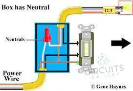
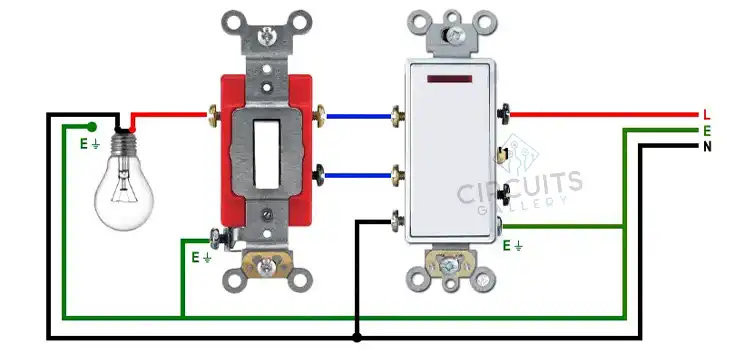
Figure 1: Connecting the wires
- Power Supply Connection:
To connect the power supply, follow these steps:
- Connect the black wire from the 277 V power supply to the “line” terminal in the light switch box.
- Connect the white wire from the power supply to the white wire from the cable going to the light fixture in the switch box.
- Connect the green or bare wire from the power supply to the ground terminal in the switch box.
- Grounding: Ensure that all metal boxes, light fixtures, and switches are grounded properly.
- Secure Connections: Use wire nuts to secure all wire connections, and ensure there are no exposed wires or loose connections.
- Test the Circuit: Turn on the power supply and test the light switch to ensure it controls the light fixture as intended. Once everything is working correctly, secure the switch box, cover it with a switch plate, and patch up any holes in the wall.
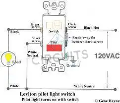
Figure 2: A wiring Diagram.
Safety Regarding 277v Light Switch Wiring Diagram
There are some important safety regards for a wiring diagram. Here are some important rules that should be followed:
- Ensure that you have the necessary knowledge and training to work with electrical systems.
- Before drawing the diagram or working on any electrical component, turn off the power to the circuit at the source
- Use lockout procedures to prevent the circuit from being accidentally energized. Use a voltage multimeter to confirm that.
- Ensure you have the correct tools and equipment for the task, including insulated screwdrivers and pliers designed for electrical work
- Keep a record of your wiring diagram and any modifications made to the electrical system
Frequently Asked Questions and Answers
Why is a Wiring Diagram Important?
Wiring diagrams provide a clear and visual representation of how components are connected in a circuit. They serve as a standardized form of documentation that can be easily understood by engineers. This is crucial for several reasons such as troubleshooting, maintenance, repair, and future modifications.
How is a 3-way Light Switch Wired?
A 3-wire NM connects the traveler terminals of the first and second 3-way switches. Traveler wires are interchangeable on each switch. The common terminal of the second 3-way switch connects to the light fixture(s). The white neutral wires are connected in each switch box.
What happens if Neutral is Not Grounded?
If the grounded (neutral) service wire is opened or not supplied at all, unwanted neutral current will flow on metal portions of the electrical system. Thus, Dangerous voltage will be present, posing a risk of electric shock.
Conclusion
With the proper tools and knowledge, a 277v light switch diagram can be drawn. However, doing any electrical work has a lot of potential risks. Therefore, proper caution and safety measures should be followed and it’s best to seek the assistance of a qualified electrician or engineer to ensure safety and integrity.
Subscribe to our newsletter
& plug into
the world of circuits