3 Wire Brushless Motor Wiring Diagram (Complete Guideline)
Three wires are essentially present in a three-wire brushless motor for control and power purposes. These motors may be used for a variety of everyday applications, including cooling fans for computers, RC cars, and drones.
A brushless motor has three wires that are color-coded. They often have yellow insulation and are red, black, and white in hue.
You will find detailed information on brushless motor wire specifications and a thorough review of the wiring schematic for a three-wire brushless motor in this article.
Brushless Motor Pin Configuration
This table describes each pin configuration.
| Pin name | Description |
| A | connects to phase 1 |
| B | connects to phase 2 |
| C | connects to phase 3 |
Color Specification of Wires
Red (or Yellow): This wire is basically used for the purpose of supplying power. This wire is named as positive or hot wire. It provides the main voltage to the motor.
White (or something Blue or Green): This wire serves to control or signal purposes. It basically controls the motor speed and direction with the help of pulse width modulation (PWM) or other control signals from an electronic speed controller (ESC).
Black: This wire is typically a common wire or ground wire. It provides a return path for the current by completing the circuit.
Wiring Diagram of 3-Wire Brushless Motor
Let’s have a look at the wiring diagram taking each connection separately.
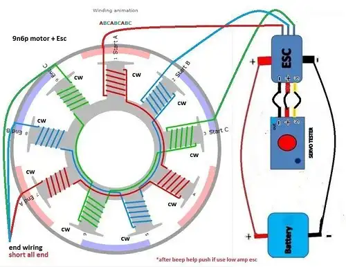
Figure 1: Wiring Diagram of a 3-Wire Brushless Motor
1. Connect the Power Supply (Red or Yellow Wire)
Connect the red wire or yellow wire to the positive voltage source. The voltage source can be a battery or power supply depending on the application.
2. Connect the Common Wire
Connect the black wire or common wire to the ground terminal of your power supply which will complete the circuit.
3. Connect the Control Wire
Connect the white wire to the control output of the motor controller. This will control the speed and direction of the motor.
4. Insulation and Security
Check the connections before finalizing the circuit to ensure that all the wires are insulated to prevent short circuits.
Frequently Asked Questions and Answers
Are All Brushless Motors 3-Phase?
Although other numbers of phases can be used to build brushless motors, three-phase brushless motors are the most frequent. Small cooling fans that only require one or two phases are an exception. A brushless motor’s three windings are linked either in a “delta” or a “star” pattern.
Why Is 3-Wire Control Used for Motors?
Because machinery won’t turn on automatically when power is restored, the 3-wire control circuit offers the operator far greater safety than the 2-wire control circuit.
Where to Use the Brushless Motors
When a project calls for modest startup costs, we mainly employ the brushless controller. This is why it’s highly favored—it’s an affordable, easily accessible motor. 1 The 3-phase controller’s availability allows us to precisely regulate the motor’s speed.
Additionally, because the driver modules are simple to use, we utilize this motor with many of them. We can simply control the engine speed using these driver modules.
Conclusion
In drones and aircraft, the brushless motor is incredibly effective. Since brushless motors come in a variety of speeds, it is important to choose them wisely. Before buying or using the product, you should carefully read and comprehend the datasheet. Also, everyone should know the wiring diagram perfectly before further application.
Subscribe to our newsletter
& plug into
the world of circuits