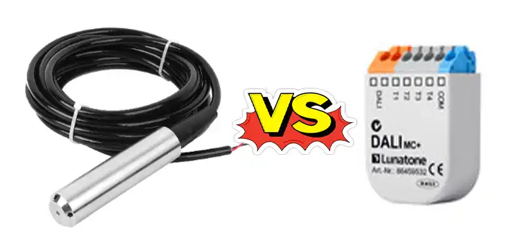
4-20mA vs 0-10V | ULTIMATE COMPARISON
The 4-20mA signal, a current loop standard, offers higher accuracy and noise immunity, making it suitable for industrial environments, while the 0-10V signal, a voltage-based option, is simpler with potentially lower initial costs, yet its susceptibility to interference and higher power consumption may vary across applications.
Let’s do a aspect-by-aspect comparison.

Exploring 4-20mA and 0-10V Signals
The 4-20mA signal is a resilient current loop standard spanning 4mA to 20mA, favored for industrial applications, while the 0-10V signal, ranging from 0V to 10V, is widely used for its simplicity and device compatibility across industries.
4-20mA Signal
The 4-20mA signal is a current loop standard used extensively in industrial applications. It represents a range of values where 4mA usually corresponds to the minimum or zero value, while 20mA signifies the maximum or full-scale value.
This signal type is known for its robustness against electrical interference and its ability to transmit signals over long distances without significant loss.
0-10V Signal
Conversely, the 0-10V signal operates on a voltage range from 0 volts, which typically denotes the minimum or zero value, to 10 volts, indicating the maximum or full-scale value. This signal type is prevalent in various industries due to its simplicity and compatibility with many devices.
Comparison Between 4-20mA & 0-10V
Here’s a detailed comparison between the 4-20mA and 0-10V signals across various parameters:
1. Signal Type and Range
4-20mA Signal
– Type: Current loop signal.
– Range: Represents values from 4mA (minimum) to 20mA (maximum).
0-10V Signal
– Type: Voltage-based signal.
– Range: Spans from 0 volts (minimum) to 10 volts (maximum).
2. Accuracy and Resolution
4-20mA Signal
– Advantages: Offers higher accuracy and finer resolution due to its current-based nature, allowing for precise measurements.
0-10V Signal
– Considerations: Provides good accuracy but might have slightly lower resolution compared to the 4-20mA signal, especially in noisy environments or over long distances.
3. Noise Immunity and Signal Integrity
4-20mA Signal
– Advantages: Highly immune to electrical noise, making it suitable for noisy industrial environments. Maintains signal integrity over long cable runs with minimal degradation.
0-10V Signal
– Considerations: More susceptible to electrical interference and voltage drops over extended distances, potentially impacting signal quality.
4. Wiring Complexity and Energy Efficiency
4-20mA Signal
– Advantages: Requires less wiring due to the current loop configuration, reducing installation complexity and costs. Consumes less power, enhancing energy efficiency.
0-10V Signal
– Considerations: Might involve more wiring compared to the current loop, potentially increasing installation complexity and costs. Higher voltage levels might consume more power.
5. Compatibility and Industry Standards
4-20mA Signal
– Advantages: Widely accepted as an industry-standard in many industrial sectors, ensuring compatibility with various devices and systems.
0-10V Signal
– Considerations: Also commonly used and compatible with several devices, but its prevalence might vary across different industries or applications.
6. Safety and Hazardous Environments
4-20mA Signal
– Advantages: Considered safer in hazardous environments due to its lower current levels, reducing the risk of sparking and ignition.
0-10V Signal
– Considerations: Higher voltage levels might pose additional risks in certain hazardous environments.
7. Cost and Maintenance
4-20mA Signal
– Considerations: Initial setup might involve higher costs due to specialized components but tends to have lower long-term maintenance expenses.
0-10V Signal
– Advantages: Typically, simpler and may have lower initial setup costs, but maintenance expenses might vary based on system complexity and requirements.
4-20mA vs 0-10V | At A Glance
| Parameter | 4-20mA Signal | 0-10V Signal |
| Signal Type and Range | Current loop, 4mA to 20mA | Voltage-based, 0V to 10V |
| Accuracy and Resolution | Higher accuracy, finer resolution | Good accuracy, slightly lower resolution |
| Noise Immunity | Highly immune to noise, maintains integrity | More susceptible to interference, potential voltage drops |
| Wiring Complexity | Requires less wiring, lower complexity | May involve more wiring, potentially higher complexity |
| Energy Efficiency | Consumes less power | Voltage levels might consume more power |
| Compatibility | Industry standard, widely accepted | Commonly used, compatibility may vary |
| Safety in Hazardous Env. | Safer due to lower current levels | Higher voltage may pose risks in certain environments |
| Cost and Maintenance | Higher initial setup costs, lower maintenance | Simpler setup, maintenance costs may vary |
Frequently Asked Questions
What safety considerations should be made when choosing between these signals?
In hazardous environments, the 4-20mA signal might be preferable due to its lower current levels, reducing the risk of sparking and ignition compared to higher voltage levels of 0-10V signals.
Can these signals be easily converted or interfaced with each other?
Yes, signal converters and interfaces are available to convert between 4-20mA and 0-10V signals, facilitating compatibility between devices that use different signal standards.
Conclusion
Both the 4-20mA and 0-10V signals have their unique strengths and weaknesses. Ultimately, understanding these signal standards empowers engineers and technicians to make informed decisions, ensuring efficient and reliable operation of industrial systems.
Subscribe to our newsletter
& plug into
the world of circuits