Skip to content
Circuits Gallery
  • Home
  • BasicsExpand
    • Wiring
    • Op-Amp
    • Circuitry
    • Oscilloscope
    • Conductivity
    • Components
  • MicroControllerExpand
    • Arduino
    • PIC
    • Simulation
  • ProjectExpand
    • Using 555 Timer
  • DigitalExpand
    • Communication
  • Submit Project
Circuits Gallery

Author: Charles Clark

A seasoned electronics enthusiast, Charles Clark is a key contributor to Circuits Gallery. From basic components to advanced microcontroller projects, Charles simplifies complex concepts with ease. His writings are a blend of expertise and passion, making electronics accessible to all. Whether it's circuitry or digital communication, Charles is the voice you can trust.
Facebook Twitter Instagram
What Diode to Use for 12V | In-Depth Guide
Components

What Diode to Use for 12V | In-Depth Guide

By

Use diode 1N5400 or 1N5402 up to 1N4008 for 12V. All these diodes are rated for a 3 Amp rating. Diodes for such currents can have a significant voltage drop. The voltage drop in a tiny silicon diode working at…
Read More What Diode to Use for 12V | In-Depth GuideContinue

6 Wire Voltage Regulator Wiring Diagram | A Comprehensive Guide
Wiring

6 Wire Voltage Regulator Wiring Diagram | A Comprehensive Guide

By

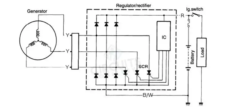
Connect the voltage regulator’s Black wire to a suitable chassis ground to wire a 6-wire voltage regulator. Connect the voltage regulator’s green wire to a switched +12VDC power source. A rectifier or voltage regulator is a device that transforms alternating…

Read More 6 Wire Voltage Regulator Wiring Diagram | A Comprehensive GuideContinue

WH5 120 L Wiring Diagram | Explained
Wiring

WH5 120 L Wiring Diagram | Explained

By

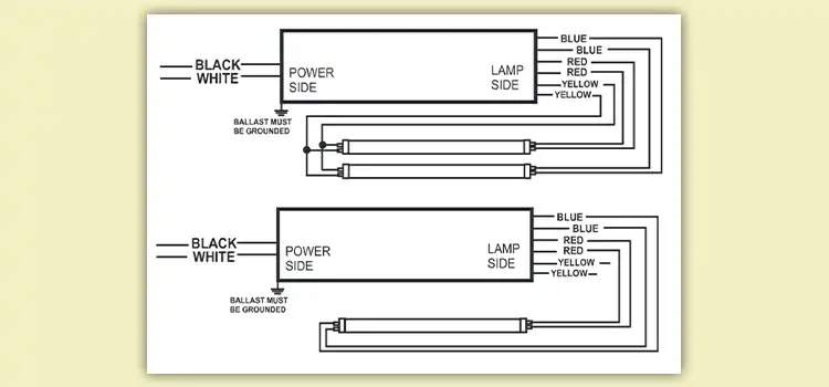
The WH5 120L, a versatile ballast by Fulham Co., Inc., requires correct wiring for optimal performance. Its diagram uses symbols like L (hot wire), N (neutral), G (ground), and R, Y, B, and W for specific wires.  The specific wiring…

Read More WH5 120 L Wiring Diagram | ExplainedContinue

How to Test an Amplifier with an Oscilloscope | A Comprehensive Guide
How To | Oscilloscope

How to Test an Amplifier with an Oscilloscope | A Comprehensive Guide

By

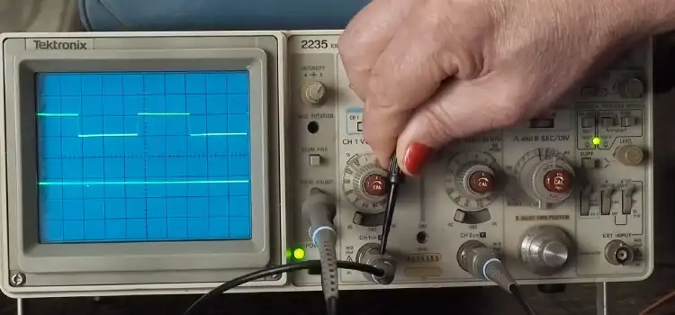
Oscilloscope testing of amplifiers is a useful method for assessing their performance and identifying problems with audio systems. An oscilloscope gives you the ability to see electrical impulses and measure different parameters, which helps you understand how the amplifier behaves. …

Read More How to Test an Amplifier with an Oscilloscope | A Comprehensive GuideContinue

What Amp GFCI for Bathroom | Answered
Basics

What Amp GFCI for Bathroom | Answered

By

The bathroom, a place of tranquility and rejuvenation, is also one of the most functional spaces in a home. Amidst the design considerations and aesthetic choices, safety should be a prime concern. Ground Fault Circuit Interrupters (GFCIs) are an essential…

Read More What Amp GFCI for Bathroom | AnsweredContinue

How to Wire a Subpanel to Another Subpanel | A Step-by-Step Guide
How To | Wiring

How to Wire a Subpanel to Another Subpanel | A Step-by-Step Guide

By

Indeed, wiring a subpanel to another subpanel is possible and often a necessity in expanding electrical systems. Expanding your electrical system by adding a subpanel to another subpanel requires precision, caution, and adherence to safety protocols.  We’ll outline the steps…

Read More How to Wire a Subpanel to Another Subpanel | A Step-by-Step GuideContinue

How to Stop Relay Chatter | Harnessing Silence
How To

How to Stop Relay Chatter | Harnessing Silence

By

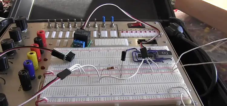
Relay chatter, often characterized by a rapid clicking or buzzing sound, is a common issue faced by electrical engineers and enthusiasts alike. It is caused by the oscillation of a relay’s armature between the energized and de-energized states.  This oscillation…

Read More How to Stop Relay Chatter | Harnessing SilenceContinue

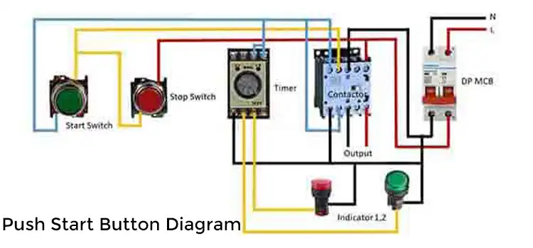
Push Start Button Diagram | Guidelines
Wiring

Push Start Button Diagram | Guidelines

By

The push start button system consists of key components: the key fob for wireless access, the start/stop button as the ignition trigger, an antenna ring/receiver for signal detection, and the Engine Control Module (ECM) managing crucial functions.  The wiring diagram…

Read More Push Start Button Diagram | GuidelinesContinue

How to Wire Emergency Lighting Circuit Diagram | A Comprehensive Guide
How To | Wiring

How to Wire Emergency Lighting Circuit Diagram | A Comprehensive Guide

By

An emergency lighting system needs lights, backup power, controls, wiring, monitoring tools, supporting items, and compliance elements. Detailed documentation and manuals accompany these components for proper installation and maintenance. This step-by-step guide outlines the installation of a compliant and reliable…

Read More How to Wire Emergency Lighting Circuit Diagram | A Comprehensive GuideContinue

Page navigation

Previous PagePrevious 1 … 18 19 20 21 22 … 29 Next PageNext
Circuits Gallery
Join Our Community:

Quick Links

  • About Us
  • Privacy Policy
  • Terms and Conditions
  • Submit Your Project
  • Contact Us

Our Story

Our journey designing innovative devices had immersed us in convoluted electronics. We realized mastery doesn't require elite degrees or industry secrets—just knowledge presented coherently. We became devoted to unraveling even quantum-complex circuits, diagram by diagram, so anyone eager to learn can unlock these secrets. By simplifying electronics fundamentals, we hope to ignite innovation in generations to come.

© Copyright 2025 Circuits Gallery | All Rights Reserved.

  • Home
  • Basics
    • Wiring
    • Op-Amp
    • Circuitry
    • Oscilloscope
    • Conductivity
    • Components
  • MicroController
    • Arduino
    • PIC
    • Simulation
  • Project
    • Using 555 Timer
  • Digital
    • Communication
  • Submit Project
Search