Binary Phase Shift Keying (BPSK) Modulation Using cd4016 With Simulated Output Waveform
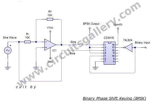
In binary phase-shift keying (BPSK), the phase of a carrier is changed according to the digital pulses signal. BPSK modulator is a phase modulator. Here the transmitted signal is a sinusoid of fixed amplitude. It has one fixed phase when the data is at one level and when the data is at the other level, the phase is shifted by 180 degrees. The binary phase-shift keying method has a variety of applications in digital communications systems such as the wireless LAN standard, IEEE 802.11, Digital modems, wireless telephone networks, etc. Differential phase-shift keying (DPSK) is another type of phase-shift keying technique that depends on the difference between successive phases. DPSK can be significantly simpler to implement than ordinary PSK since there is no need for the demodulator to have a copy of the reference signal to determine the exact phase of the received signal (it is a noncoherent scheme). Here is the practical circuit of BPSK, it is built around CD4016 and 741 Op-amp.
Circuit Diagram of Binary Phase Shift Keying (BPSK)
Components Required for BPSK Modulation Using cd4016
- Resistors (10kΩ)
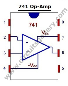
- 741 Op-Amp
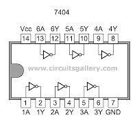
- CD 4016 IC
- Not Gate 7404
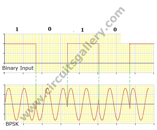
Output Waveform
How Does It Work?
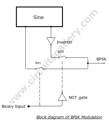
- Op-amp inverting amplifier with gain 1 is used to invert the phase of the input sine wave.
- A sine wave can be obtained from a function generator or using an RC phase shift oscillator.
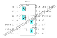
- Two switches inside the quad analog switch CD 4016 are used in the circuit. When the enabled input of one gate is high, then the input will appear at the output
- When the binary data is 1, a sine wave is switched to output because the sine wave is connected to the 1st switch and the binary data is applied to enable the pin (13th pin) of the 1st switch.
- When binary data is 0, the 1st switch is disabled and the 2nd switch is enabled using no gate arrangement. Thus we get inverted sine at the output.
- The output pins of both first and second switches are shorted and the output is taken from them. The block diagram is self-explanatory.
Components Pinout
Conclusion
Binary Phase Shift Keying (BPSK) Modulation is an important part of any communication project. Here we have seen how to build it using simple components within moments.
Subscribe to our newsletter
& plug into
the world of circuits