Can You Crimp Solid Wire? | Safest Way to Crimp
Yes, a solid wire can be crimped. Crimping is the process of joining two terminals of metal. Crimping a wire means joining a wire to a wire or a wire to a terminal without using soldering. In this process, a wire is deformed and then compressed to the end of the terminal to bind them.
A crimping tool is used to crimp a wire. There are several types and categories of crimping tools used for crimping. For the different requirements of power different categories of crimp tools are used. Those are handheld, electrical, hydraulic, benchtop, and pneumatic.
Can You Use Crimp Connectors on Solid Wire?
A crimp connector is a solder-less connector used in an electrical circuit. One of the most used connectors is barrel and open barrel type which consists of a cylindrical metal opening where the wire is inserted. There are several steps to crimp connectors. These are:
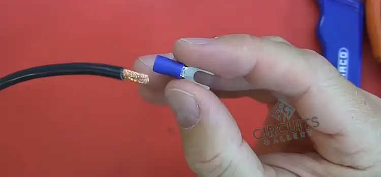
- A stripper is used to strip (remove) the insulator layer to a required portion. The required portion should be equal to the cylinder metal of a connector.
- Then insert the stripped wire inside the terminal of the connector.
- Use a crimping tool to compress the wire and the terminal to make a joint.
- Cover the joint with an isolated shrink tube and use a heat gun to shrink it over the joint.
How to Connect Solid Wire to Solid Wire?
Two solid wires can be crimped using a single connector or using two connectors (one known as a male connector and the other as a female connector). Crimp terminal connectors and barrel connectors are single connectors. And bullet connectors are two separable connectors.
If the two wires fit the cylinder metal of the connector then the wires can be connected by compressing the connector. The crimp connector has two terminals. It is used when the wire is large.
A bullet connector is used where the connection needs to be separable. Two wires are connected with two terminals. One of them is a male terminal and the other one is a female terminal. They can be connected and separated from each other.
Can You Crimp Single Core Wire?
Yes, a single core wire can be crimped if the radius fits the cylindrical metal of the connector. A barrel connector can be used to crimp. If two single core wires need to be then we can crimp terminal or bullet terminal.
How Do You Splice Solid Copper Wire?
Splicing a wire means twisting two wires to connect them. A solid copper wire can be spliced using a twist-on wire cap or nut. First strep end terminal of the wire. Insert them into the wire cap and twist the cap.
Splicing can also be done using a butt splice or using Linemace’s splice. In the lineman’s splice bend the wire at a 90-degree angle, hook them, and twist them at least 3 times. Be careful that the twisting wire does not overlap. In every joint cover, it with a shrink tube and heat it until it shrinks.
Conclusion
Crimping is important to connect a wire to a terminal. A wire can connect with another wire through crimping to avoid soldering. It is useful where joints need to be separable. A crimp connector can be used where the wire can not be connected directly. To prevent leakage shrink tube is used.
Subscribe to our newsletter
& plug into
the world of circuits