Capacitance vs Frequency | A Comprehensive Analysis
Capacitance, and frequency are two fundamental concepts that govern the behavior of electrical circuits. Understanding the relationship between capacitance and frequency is crucial for designing and analyzing various electronic circuits.
In this article, we will dive into the intricate dynamics between capacitance and frequency.
Capacitance: Storing Electrical Charge
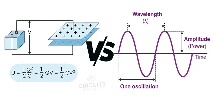
Capacitance, represented by the symbol C is the ability of a component to store an electrical charge. A capacitor consists of two conductive plates separated by an insulating material called a dielectric. When a voltage is applied, opposite charges accumulate on the plates, creating an electric field that stores energy.
The capacitance depends on the plate area, plate separation distance, and dielectric material. More plate area and a smaller separation distance lead to greater capacitance since more charge can be accumulated. Dielectric materials like ceramics increase capacitance by polarizing to enhance the electric field.
Frequency: The Rate of Oscillation
Frequency, represented by f and measured in hertz (Hz), is the number of cycles per second of an alternating current (AC) signal. It determines the wavelength and propagation of AC waves. Higher frequency corresponds to more cycles per second.
Radio waves, electrical grids, and digital signals are examples where frequency is a key parameter. Frequency ranges from extremely low frequencies of 3-30 Hz in electrical grids to microwave frequencies of gigahertz for WiFi and radars.
Capacitance and Frequency Relationship
The interaction between capacitance and frequency is governed by capacitive reactance, represented as XC. Reactance is the opposition to AC flow. For a capacitor:
XC = 1/(2πfC)
where:
- Xc is the capacitive reactance in ohms (Ω)
- f is the frequency in hertz (Hz)
- C is the capacitance in farads (F)
Impact of Frequency on Capacitor Behavior
Capacitive reactance XC is inversely proportional to frequency f. As frequency increases, reactance decreases, allowing more AC to flow through the capacitor.
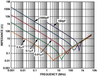
At lower frequencies, reactance is larger, impeding current flow, so the capacitor charges and discharges slowly. At higher frequencies, reactance is smaller, so the capacitor charges and discharges rapidly.
In DC circuits, capacitors block current due to infinite reactance. But in AC circuits, capacitors pass current easily at high enough frequencies.
Vector Analysis of Voltage-Current Phase
The voltage and current are out of phase in an AC capacitance circuit. The current leads the voltage by a phase angle of 90°. This results from the charging and discharging dynamics.
We can analyze this using vector diagrams. The current is taken as the reference vector. The voltage vector lags the current vector by 90° due to the capacitance. This shows the leading current phase relationship. The mnemonic “ICE” represents the current leading voltage sequence.
Effect of Frequency on Capacitor Impedance and Phase Angle
For ideal capacitors, impedance is purely from capacitive reactance XC. However real capacitors have parasitic resistance and inductance. This means the impedance has a phase angle between 0° and -90°.
For an RC series circuit:
Impedance Z = R2 + XC2
Phase angle θ = arctan(XCR)
The impedance triangle graphically shows the contribution of resistance R and capacitive reactance XC to the total impedance Z.
As frequency increases, XC decreases, so the phase angle moves closer to 0°. The capacitor starts behaving more like a resistor.
Applications Utilizing Capacitance-Frequency Interplay
The capacitance-frequency relationship has many applications:
- AC Line Filters: Large capacitances are used to pass low-frequency signals and block high frequencies.
- Tuned Circuits: Capacitors and inductors can create resonant RLC circuits to filter specific frequencies.
- Bypass/Decoupling: Small capacitors filter noise by shunting high AC frequencies to the ground.
- Timing Circuits: Capacitor charging/discharging rates set time constants for timers and oscillators.
- Impedance Matching: Capacitors can match impedances between circuits operating at different frequencies.
FAQs – Frequently Asked Questions and Answers
- What causes the capacitance of a real capacitor to change with frequency?
Answer: Real capacitors have parasitic inductance and resistance which alters impedance vs frequency. Near self-resonant frequency, inductive reactance cancels the capacitive reactance.
- Why do capacitors block DC but pass AC at high frequencies?
Answer: With DC, frequency is zero, so reactance is infinite, blocking current. With high AC frequencies, reactance nears zero, allowing current to pass.
- How does frequency affect capacitor impedance?
Answer: As frequency increases, capacitive reactance decreases, reducing capacitor impedance, and allowing more AC to flow.
To Conclude
In summary, capacitance and frequency have an inverse relationship governed by capacitive reactance. Understanding this interplay is key to properly designing and analyzing AC circuits containing capacitors. With the depth of knowledge gained here, you can now confidently leverage capacitance and frequency in your electrical engineering endeavors.
- Capacitance: Storing Electrical Charge
- Frequency: The Rate of Oscillation
- Capacitance and Frequency Relationship
- Impact of Frequency on Capacitor Behavior
- Vector Analysis of Voltage-Current Phase
- Effect of Frequency on Capacitor Impedance and Phase Angle
- Applications Utilizing Capacitance-Frequency Interplay
- FAQs - Frequently Asked Questions and Answers
- To Conclude
Subscribe to our newsletter
& plug into
the world of circuits