Car Jump Starter Circuit Diagram | How the Device Work?
Car jump starters have evolved into essential tools for each driver. These small devices permit you to quickly resume driving after a dead battery. But have you thought about what happens inside and how these practical devices work?
In this article, we’ll look at a car jump starter’s circuit diagram to uncover its key components and how to recharge your car’s battery.
What is a Car Jump Starter?
A car jump starter, also known as a jump pack, jump box, or booster pack, is a portable electronic device designed to temporarily and rapidly boost the electrical power in a dead or discharged vehicle battery so that the vehicle can start.
For drivers who get stuck because their car won’t start due to a flat or weak battery, it is an essential piece of equipment.
The standard strategy of connecting one car’s flat battery to another’s battery using battery clamps and cables has been updated to include jump starters. The method is hence called “Jump starting” or “Jump starting.”
What are the Components of Car Jump Starter Wiring Diagram?
A car jump starter wiring diagram includes:
1. Car Battery (+/-)
The vehicle’s power source with positive (+) and negative (-) terminals.
2. Jump Starter Unit (+/-)
A portable device with its own positive (+) and negative (-) terminals, used to jump-start the car.
3. Jumper Cables (Red/Black)
Cables with red (positive) and black (negative) clamps to connect the jump starter to the car battery.
4. Ignition Switch
Part of the car’s electrical system, typically in the OFF position during jump-starting.
5. Ground (Chassis)
The connection to the car’s chassis or a designated ground point for completing the circuit.
6. Connections Between Car Battery and Jump Starter
Arrows or lines indicate the path of current flow between the car battery and the jump starter.
7. Safety Features (If Any)
Additional components like surge protection or reverse polarity protection for safety.
8. Optional Accessories (Switches, Fuses, Lights)
Extra components may be present in the jump starter setup, such as switches, fuses, or indicator lights.
Circuit Diagram of Car Jump Starter
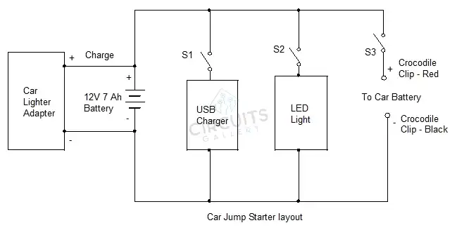
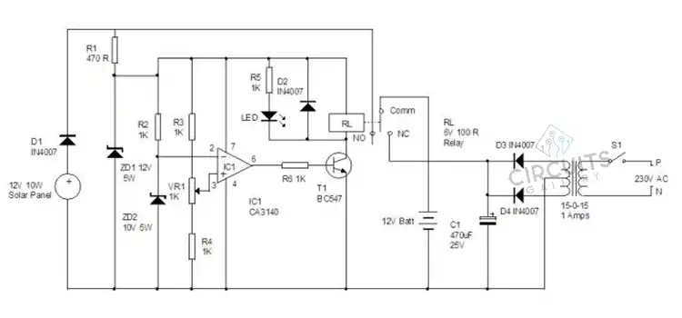
Image 1- Car Jump Starter Circuit Diagram Layout
Image 2- Car Jump Starter Wiring Diagram
How a Car Jump Starter Circuit Works?
Let’s go through how a car jump starter works when a battery is dead now that we are familiar with its circuit chart:
1. Preparation
Charge a jump starter before utilizing it. You might need to charge it sometimes, according to the item’s instruction booklet.
2. Connection
The proper battery connections on your car should receive jumper cables. The negative terminal (-) should have a black wire attached, and the positive terminal (+) should have a red cable.
3. Power On
To activate the jump starter, use the power switch.
4. Jump-Start
Your car’s battery receives the necessary energy from the jump starter’s battery, which is currently dispensing a continuous 12 volts of power. The kick-start your car needs to start its engine is provided by this power surge.
5. Removal
After starting your automobile, gently unplug the jumper wires by first removing the black (negative) cable, and then the red (positive).
6. Turn Off
To protect the jump starter’s battery for later usage, do not forget to turn it off with the power switch.
FAQs – Frequently Asked Questions and Answers
Are there any additional safety features in modern jump starter units that are not shown in the circuit diagram?
Yes, reverse polarity, short-circuit, and overcurrent protection are among the many safety features that modern jump starters usually offer. These characteristics are typically not depicted in the circuit design, despite the fact that they are essential for secure jump-starting.
Are there different types of jump starter circuit diagrams for different vehicles?
The majority of cars have the same jump-starting principles, although depending on the electrical system, where the battery is located, and the vehicle’s engine sort, the circuit diagram may change. It’s crucial to refer to the owner’s manual for your particular vehicle or the jump starter manufacturer for instructions.
Is it safe to jump-start a car in adverse weather conditions, such as heavy rain or extreme cold?
Jump-starting a car in extreme weather may be dangerous due to an increased chance of electrical arcing or wires slipping when being connected. If at all possible, try to jump-start your car in a dry, covered place while utilizing utmost caution. Check the jump starter’s handbook for details on how to utilize it specifically in different weather conditions.
Conclusion
The ability to jump-start a car is crucial when dealing with dead battery issues. Following the manufacturer’s recommendations and putting safety first will guarantee an effective and secure jump-start. If you have the right information and tools, you can remedy a dead battery issue fast and drive with assurance again.
Subscribe to our newsletter
& plug into
the world of circuits