Skip to content
Circuits Gallery
  • Home
  • BasicsExpand
    • Wiring
    • Op-Amp
    • Circuitry
    • Oscilloscope
    • Conductivity
    • Components
  • MicroControllerExpand
    • Arduino
    • PIC
    • Simulation
  • ProjectExpand
    • Using 555 Timer
  • DigitalExpand
    • Communication
  • Submit Project
Circuits Gallery

Wiring

What Happens if the Live and Neutral Wires Are Swapped? – Is It Wise to Reverse the Wires?
Wiring

What Happens if the Live and Neutral Wires Are Swapped? – Is It Wise to Reverse the Wires?

By

In electrical wiring, the live wire carries current from the power source while the neutral wire returns current to complete the circuit. Swapping these wires can lead to reversed polarity, resulting in risks of injury, equipment damage, and even fire. …

Read More What Happens if the Live and Neutral Wires Are Swapped? – Is It Wise to Reverse the Wires?Continue

Mobility Scooter Wiring Diagram | Navigate Your Mobility Scooter’s Wiring
Wiring

Mobility Scooter Wiring Diagram | Navigate Your Mobility Scooter’s Wiring

By

Mobility scooters have developed into indispensable tools for those with mobility issues, giving them more mobility and independence. Understanding the wiring schematics of these scooters is essential for maintenance and troubleshooting since they depend on complex electrical systems to operate…

Read More Mobility Scooter Wiring Diagram | Navigate Your Mobility Scooter’s WiringContinue

Doerr Electric Motor LR22132 Wiring Diagram: LR22132 Motor Wiring
Wiring

Doerr Electric Motor LR22132 Wiring Diagram: LR22132 Motor Wiring

By

Electric motors are the workhorses of modern industry, powering everything from household appliances to large machinery. Among the multitude of electric motor manufacturers, Doerr stands out for its reliability and efficiency. For anyone delving into the world of electrical appliances…

Read More Doerr Electric Motor LR22132 Wiring Diagram: LR22132 Motor WiringContinue

1-way vs 2-way vs 3-way Switch – What’s the Difference? | How do Switches Differ?
Basics | Circuitry | Wiring

1-way vs 2-way vs 3-way Switch – What’s the Difference? | How do Switches Differ?

By

The key differences between these 3 switches are a lot more than that of the mentioned heading above. The contrasts exist based on construction, terminals, controlling location, and applications of these switches individually. A one-way switch can be controlled from…

Read More 1-way vs 2-way vs 3-way Switch – What’s the Difference? | How do Switches Differ?Continue

6 Wire Voltage Regulator Wiring Diagram | A Comprehensive Guide
Wiring

6 Wire Voltage Regulator Wiring Diagram | A Comprehensive Guide

By

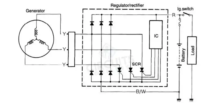
Connect the voltage regulator’s Black wire to a suitable chassis ground to wire a 6-wire voltage regulator. Connect the voltage regulator’s green wire to a switched +12VDC power source. A rectifier or voltage regulator is a device that transforms alternating…

Read More 6 Wire Voltage Regulator Wiring Diagram | A Comprehensive GuideContinue

WH5 120 L Wiring Diagram | Explained
Wiring

WH5 120 L Wiring Diagram | Explained

By

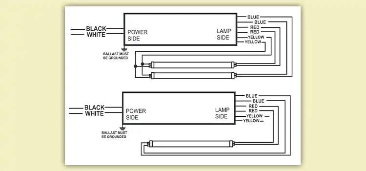
The WH5 120L, a versatile ballast by Fulham Co., Inc., requires correct wiring for optimal performance. Its diagram uses symbols like L (hot wire), N (neutral), G (ground), and R, Y, B, and W for specific wires.  The specific wiring…

Read More WH5 120 L Wiring Diagram | ExplainedContinue

How to Wire a Subpanel to Another Subpanel | A Step-by-Step Guide
How To | Wiring

How to Wire a Subpanel to Another Subpanel | A Step-by-Step Guide

By

Indeed, wiring a subpanel to another subpanel is possible and often a necessity in expanding electrical systems. Expanding your electrical system by adding a subpanel to another subpanel requires precision, caution, and adherence to safety protocols.  We’ll outline the steps…

Read More How to Wire a Subpanel to Another Subpanel | A Step-by-Step GuideContinue

Push Start Button Diagram | Guidelines
Wiring

Push Start Button Diagram | Guidelines

By

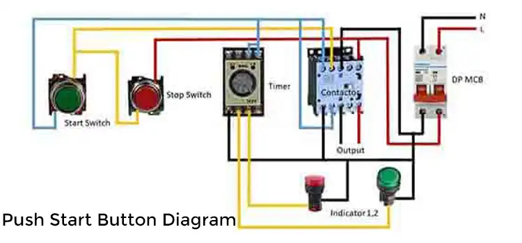
The push start button system consists of key components: the key fob for wireless access, the start/stop button as the ignition trigger, an antenna ring/receiver for signal detection, and the Engine Control Module (ECM) managing crucial functions.  The wiring diagram…

Read More Push Start Button Diagram | GuidelinesContinue

How to Wire Emergency Lighting Circuit Diagram | A Comprehensive Guide
How To | Wiring

How to Wire Emergency Lighting Circuit Diagram | A Comprehensive Guide

By

An emergency lighting system needs lights, backup power, controls, wiring, monitoring tools, supporting items, and compliance elements. Detailed documentation and manuals accompany these components for proper installation and maintenance. This step-by-step guide outlines the installation of a compliant and reliable…

Read More How to Wire Emergency Lighting Circuit Diagram | A Comprehensive GuideContinue

Page navigation

Previous PagePrevious 1 … 3 4 5 6 7 … 9 Next PageNext
Circuits Gallery
Join Our Community:

Quick Links

  • About Us
  • Privacy Policy
  • Terms and Conditions
  • Submit Your Project
  • Contact Us

Our Story

Our journey designing innovative devices had immersed us in convoluted electronics. We realized mastery doesn't require elite degrees or industry secrets—just knowledge presented coherently. We became devoted to unraveling even quantum-complex circuits, diagram by diagram, so anyone eager to learn can unlock these secrets. By simplifying electronics fundamentals, we hope to ignite innovation in generations to come.

© Copyright 2025 Circuits Gallery | All Rights Reserved.

  • Home
  • Basics
    • Wiring
    • Op-Amp
    • Circuitry
    • Oscilloscope
    • Conductivity
    • Components
  • MicroController
    • Arduino
    • PIC
    • Simulation
  • Project
    • Using 555 Timer
  • Digital
    • Communication
  • Submit Project
Search