In-Depth Guide Of Class B Fire Alarm Wiring Diagram
In the realm of fire safety and emergency preparedness, a Class B fire alarm system is an absolute necessity. To ensure its effectiveness, understanding the Class B fire alarm wiring diagram is vital.
In this comprehensive guide, we will delve into the intricacies of Class B fire alarm wiring, providing you with a step-by-step overview, essential components, and insights into its significance.

Deciphering Class B Fire Alarm Systems
Class B fire alarm systems are a cornerstone of fire safety in commercial and industrial settings. Distinguished by their dual loops, Class B systems enable redundancy, ensuring reliability even when a fault arises. This system is characterised by an “initiating device loop” and a “notification appliance loop.”
Class B vs. Class A Fire Alarm Systems
Class A systems, offering higher levels of redundancy, can sustain functionality even if a single wire breaks. However, Class B systems provide a cost-effective alternative, widely adopted in practical applications.
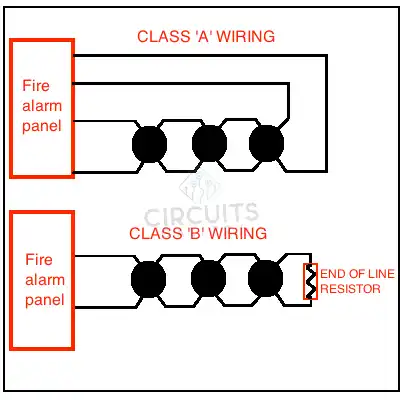
Figure: Class A vs Class B Fire Alarm System.
Working Principle Of Class B Fire Alarm System
The working flow from detection to notification of the class B fire alarm system is given below:
- Smoke Detectors: Employed to detect the presence of smoke particles, signalling potential fire outbreaks.
- Heat Detectors: Triggered by elevated temperatures, these devices offer a complementary detection method.
- Pull Stations: Manual devices for fire initiation, pivotal in emergency situations.
- Control Panel: The central intelligence, processing signals from detectors and initiating notification appliances.
- Notification Appliances: Including horns, strobes, and bells, these devices broadcast alerts during emergencies.
A Step-by-Step Guide to Class B Fire Alarm Wiring
Precision in wiring is the lifeblood of Class B fire alarm systems. It ensures that signals from initiating devices are accurately transmitted to the control panel. The heart of the system comprises smoke detectors, heat detectors, pull stations, control panels, and notification appliances.
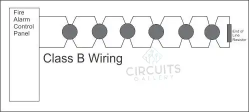
Figure: Class B Fire Alarm Wiring.
Power Supply Precision
Power supply intricacies encompass backup batteries and their distribution. These batteries ensure system functionality, especially during power outages, when reliability is paramount.
Initiating Devices and Notification Appliances
Wiring initiating devices and notification appliances demands meticulous attention. This step determines the coherence and functionality of the entire system, and proper wiring guarantees quick response during a fire emergency.
The Role of Control Panels
Control panels act as the central nervous system of the Class B fire alarm system. They receive signals from initiating devices, process information, and activate notification appliances, orchestrating an effective response.
Decoding Wiring Color Codes
Interpreting wiring color codes is crucial for identifying various circuits and their functions within the system. This system helps technicians pinpoint and troubleshoot issues with precision.
The Significance of Redundancy in Class B Systems
Redundancy, achieved through dual loops, is integral to Class B systems. Redundancy ensures that a single fault in one loop will not compromise the system’s overall functionality.
FAQs
1. Are there specific regulations governing Class B fire alarm systems?
Compliance with local fire codes and regulations is crucial for a legal and safe installation.
2. How do control panels function in Class B fire alarm systems?
Control panels receive signals from initiating devices, process the information, and activate notification appliances.
3. How are power supplies managed in Class B fire alarm systems?
Backup batteries are employed to ensure system functionality, especially during power outages.
Conclusion
In conclusion, the thorough understanding and meticulous implementation of a Class B fire alarm wiring system are central to safeguarding life and property in the event of a fire emergency. Such systems offer an unmatched level of reliability and effectiveness.
Subscribe to our newsletter
& plug into
the world of circuits