Dayton Blower Motor Wiring Diagram | A Step-by-Step Guide
Dayton offers single-phase and three-phase blower motors in a range of sizes and speeds. Properly wiring them requires following the correct wiring diagram that matches the specific motor model.
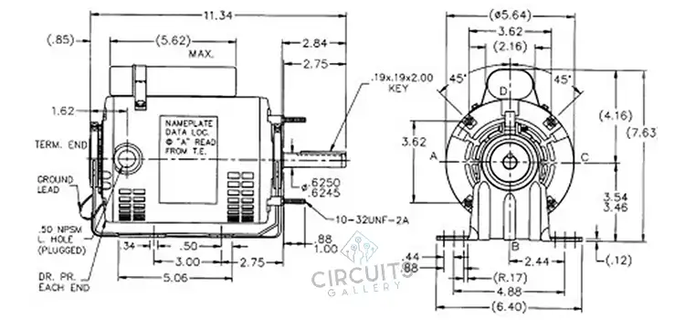
The wiring diagram is usually printed on the motor label or available in the product documentation. So, let’s discuss the Dayton Blower Motor Wiring Diagram.
Single Phase Dayton Blower Motor Wiring Diagram
Key things to determine are:
- Motor voltage and phase
- Number of wiring leads
- Required wiring connections
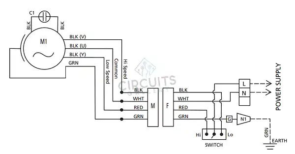
Where:
M1 Fan Motor 1
C1 Run Capacitor Fan Motor 1
N1 Wire nut
– – – Field wiring
Overview
Power leads, typically black and white wires, supply electricity from the circuit breaker panel to the motor. Auxiliary components, like capacitors, aid in starting and running single-phase motors. These are connected to the motor using wires, often red.
Additional wires may link to external switches for motor control or speed tap wires for adjusting operating speeds, such as high, medium, and low. These taps alter winding connections to change the speed.
Terminal Identification
- T1 – Black- High-speed winding
- T2 – White – Common
- T3 – Red – Low-speed winding
- BLK – Main Power Supply
- Ground – Green
- C1 – Black – Capacitor
Three-Phase Dayton Blower Motor Wiring Diagram Overview
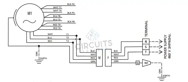
Where:
M1 Fan Motor 1
N1 Wire nut
– – – Field wiring
Overview
Three-phase motors have three power lead wires labelled T1, T2, and T3, supplying power directly to the motor windings. Grounding the motor frame ensures safety; this is done using a green ground wire connected to the motor housing.
Unlike single-phase motors, three-phase motors don’t require capacitors. Additional wires are usually for external controls. The crucial distinction is that single-phase motors need capacitors, while three-phase motors receive phased power directly from the source.
Terminal Identification
- BLK – Black wire, likely the main power supply line
- P4, P5, P6 – Power terminals, where the three power phases connect
- WHT – White wire, usually the second main power supply line
- T7, T4 – Auxiliary winding terminals
- BLU – Blue wire, often a speed tap or start winding
- T8, T5 – Connection points for blue wire
- RED – Red wire, maybe a brake winding or speed tap
- T9, T6 – Terminals for red wiretap
- T1 – White – Medium speed winding
- T2 – Blue – High-speed winding
- T3 – Red – Low-speed winding
- Ground – Green
The exact diagram varies across motor models depending on the features.
Wiring Procedure
Here are the wiring procedure steps for Dayton blower motors:
- Check the motor nameplate for the correct voltage and phase.
- Select proper gauge wire based on motor amp rating and wire run length.
- Run wires from the power source to the motor. Use flexible conduit if necessary
- Connect the ground wire to the ground terminal on the motor.
- Connect main power wires to motor terminals – Line to L1, Neutral to L2 for single-phase motor, and three-phase terminals on the motor per diagram – L1, L2, L3 for three-phase motor.
- Connect capacitor wires to motor capacitor terminals. Observe polarity if marked (For single phase).
- Connect any other auxiliary wires like taps or switches according to the diagram.
- Ensure solid tight connections. Double-check connections against the wiring diagram.
- Test the direction of rotation before full installation.
Testing the Motor
Once wired, confirm the correct operation by verifying:
- Motor spins freely by hand
- Correct rotation direction
- Motor current draw is within the nameplate rating
Typical Wiring Issues
Some common wiring mistakes include:
- Incorrect lead connections
- Loose connections
- Wrong voltage applied
- Wrong capacitor value
- Short circuits
Frequently Asked Questions and Answers (FAQs)
1. Why Does My Motor Hum but Not Turn?
If a single-phase motor hums but fails to start, a bad capacitor is often the cause. Replace the run capacitor with one of the proper capacitance values for the motor according to the wiring diagram.
2. How Do I Wire for Multiple Speeds?
Motors with speed taps or multi-winding options require connecting the leads to an external speed switch according to the wiring diagram. Slow speeds use less winding, and faster uses more winding.
3. What if Some Leads on My Motor Are Different Colours Than the Diagram?
Sometimes actual lead colour may vary from the diagram. It’s best to trace the wires from the internal connections shown to determine what each lead connects to rather than relying solely on colour.
To Conclude
Understanding and properly following Dayton blower motor wiring diagrams is crucial for installation and troubleshooting. Following the correct wiring diagram for the specific motor model ensures safe and trouble-free operation. Paying close attention to wiring details goes a long way toward a successful installation.
Subscribe to our newsletter
& plug into
the world of circuits