Skip to content
Circuits Gallery
  • Home
  • BasicsExpand
    • Wiring
    • Op-Amp
    • Circuitry
    • Oscilloscope
    • Conductivity
    • Components
  • MicroControllerExpand
    • Arduino
    • PIC
    • Simulation
  • ProjectExpand
    • Using 555 Timer
  • DigitalExpand
    • Communication
  • Submit Project
Circuits Gallery
Home / Basics / Wiring / In-depth Guide Of DC Jack Wiring Diagram

In-depth Guide Of DC Jack Wiring Diagram

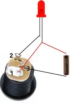
A DC jack consists of three pins: Pin 1 (positive, battery link), Pin 2 (negative), and Pin 3 (negative, linked to Pin 2). Polarity maintenance is crucial, with red denoting the positive wire (center pin) and black representing the negative or ground wire (outer sleeve) in the color-coded system. 

This precise wiring configuration ensures reliable and secure electrical connections, emphasizing the fundamental role of correct polarity in electronic device operation. Now, let’s observe in details.

DC Jack Wiring Diagram

Components of a DC Jack

To comprehend the functioning of a DC jack, a breakdown of its primary components is essential:

Pin 1: The pin is positive that is connected with the positive part of battery.

Pin 2: The pin is negative.

Pin 3: The pin is also negative and it is connected with pin 2.

Components of a DC Jack

Wiring Configuration

The significance of maintaining correct polarity cannot be overstated. Polarity, determining the positive and negative orientations, is the backbone of stable and secure electrical connections.

Wiring Configuration

Navigating the colour-coded spectrum of wires adds an artistic touch to the technical canvas. Typically, red signifies the positive wire (connected to the centre pin), while black denotes the negative or ground wire (linked to the outer sleeve).

Advanced Insights

For those seeking precision in voltage regulation, the integration of resistors becomes an artful technique. These components allow a nuanced adjustment of voltage output, catering to the specific needs of the device. Diodes should be strategically placed within the circuit, these components ensure the safety of both the device and the intricate wiring system.

FAQs

Q1. Can I reverse the polarity without consequences?

Answer: Flipping polarity risks malfunctions or damage, emphasising the importance of maintaining the correct polarity.

Q2. Are all DC jacks wired the same way?

Answer: While common standards exist, variations require adherence to device specifications for accuracy.

Q3. What happens if I use the wrong wire colours?

Answer: Mismatched colours can lead to confusion and potential circuit issues. Adherence to standard colour codes is recommended.

Conclusion

In conclusion, DC jack wiring is not merely a technical task but an art form. It empowers electronic enthusiasts to craft, troubleshoot, and innovate. As the saying goes, “knowledge is power,” and in the realm of DC jack wiring, this power translates into endless possibilities.

Table Of Contents
  1. Components of a DC Jack
  2. Wiring Configuration
  3. Advanced Insights
  4. FAQs
  5. Conclusion

Subscribe to our newsletter

& plug into

the world of circuits

    A seasoned electronics enthusiast, Charles Clark is a key contributor to Circuits Gallery. From basic components to advanced microcontroller projects, Charles simplifies complex concepts with ease. His writings are a blend of expertise and passion, making electronics accessible to all. Whether it's circuitry or digital communication, Charles is the voice you can trust.

    Facebook Twitter Instagram

    Recent Blogs

    • How to Make A 75 To 300 Ohm Matching Transformer
      How to Make A 75 To 300 Ohm Matching Transformer? | A Step by Step Guide for You
    • How to Download Circuit Wizard? | Procedure for Downloading the Latest Version
    • What Gauge Wire from Battery to Starter
      What Gauge Wire from Battery to Starter? | Choosing the Right Wire Gauge
    • What Does 50 Milliamps Look Like on a Multimeter
      What Does 50 Milliamps Look Like on a Multimeter? | Let’s Find Out
    • How Many Watts Does a 32 Inch TV Use
      How Many Watts Does a 32 Inch TV Use? | Find Out the Required Wattage for Different Brands
    • What Size Conduit for 122 Wire
      What Size Conduit for 12/2 Wire? | Choosing the Right Conduit for Your 12/2 Wire

    Browse Categories

    • Arduino
    • Basics
    • Circuitry
    • Communication
    • Components
    • Conductivity
    • Digital
    • How To
    • MicroController
    • Op-Amp
    • Oscilloscope
    • PIC
    • Project
    • Simulation
    • Using 555 Timer
    • Wiring
    Circuits Gallery
    Join Our Community:

    Quick Links

    • About Us
    • Privacy Policy
    • Terms and Conditions
    • Submit Your Project
    • Contact Us

    Our Story

    Our journey designing innovative devices had immersed us in convoluted electronics. We realized mastery doesn't require elite degrees or industry secrets—just knowledge presented coherently. We became devoted to unraveling even quantum-complex circuits, diagram by diagram, so anyone eager to learn can unlock these secrets. By simplifying electronics fundamentals, we hope to ignite innovation in generations to come.

    © Copyright 2025 Circuits Gallery | All Rights Reserved.

    • Home
    • Basics
      • Wiring
      • Op-Amp
      • Circuitry
      • Oscilloscope
      • Conductivity
      • Components
    • MicroController
      • Arduino
      • PIC
      • Simulation
    • Project
      • Using 555 Timer
    • Digital
      • Communication
    • Submit Project
    Search