Digital Counters | Johnson, Ring, and More
Digital counters are being used in many different sectors of our life. You can use it in digital clocks, analog to digital converters, frequency counters, time measurements, and many other purposes.
But if you can build your own digital counter, then you can design it according to your needs. That’s why it is always better to build a digital converter than to buy one from the market.
In this article, we’re going to show you the basics of a digital counter and provide you with some diagrams including some animations/simulations and building processes of the following digital counters –
- Johnson Digital Counter Circuit Diagram Using D Flip Flop 7474 (3 Bit/4 Bit).
- Simple 4026 Manual Digital Counter Circuit With Reset and Pause which is a LED 7-segment display counter circuit.
- Ring Counter Circuit Working Principle.
- Asynchronous Binary Up Counter Circuit With Working Procedure.
So, don’t miss the chance to make amazing digital converters yourself and quickly learn how to build them below.
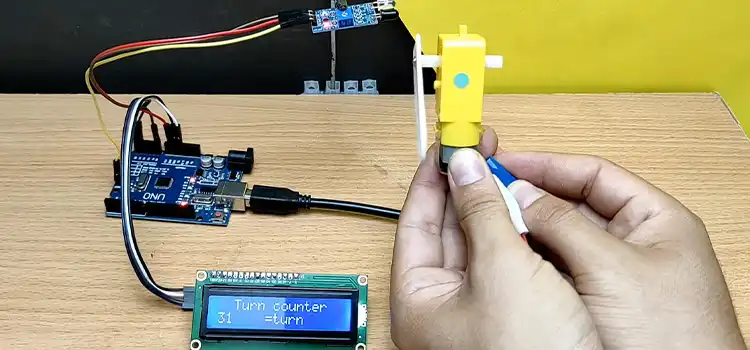
1. Johnson Digital Counter Circuit Diagram Using D Flip Flop 7474 (3 Bit/4 Bit) With Animation/ Simulation
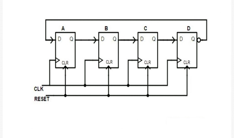
We have discussed the Johnson digital counter or Twisted Ring Counter as a synchronous shift register in this article. You can create simple dancing LED effects using this counter. Fortunately, you only need half the number of flip-flops compared to that of the standard ring counter to represent multiple states. Let’s learn more details about this digital counter below.
Johnson Digital Counter Circuit Diagram
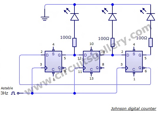
Components Required for Johnson Digital Counter with Dancing LEDs
- 7474 D flip flop x 2
- Resistors (100Ω -1/4 watt x 4)
- Astable multivibrator (3 KHz)
- LEDs x 3
Simulation | Animation | Working of Twisted Ring Counter
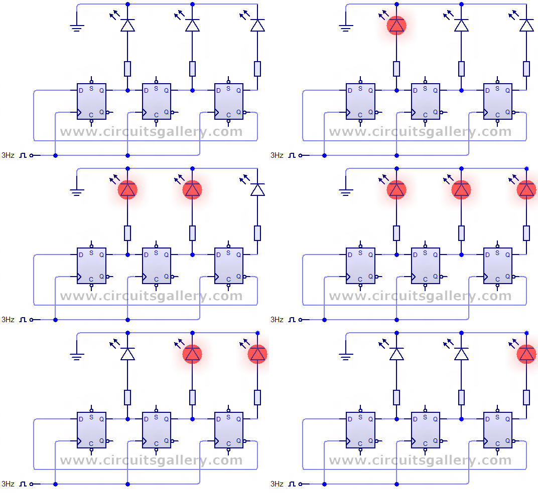
- The above circuit diagram represents a 3-bit Johnson counter using a 7474 D flip-flop. You can easily extend this circuit up to 4-bit, 5-bit, etc. by adding flip-flops after the 3rd flip-flop.
- A single 7474 IC consists of 2 flip-flops. So you need two 7474 ICs for implementing the Johnson ring counter.
- Initially, all the flip-flops are cleared. So the time inverted output (Q’) of the 3rd flip-flop is high or logic 1. This logic 1 appears at the input of the 1st flip-flop.
- During the first clock pulse, this logic 1 is transferred to the output of 1st flip-flop. Thus, the total output of the Johnson counter is 100.
- Then input of the 1st and 2nd flip-flop is logic 1. And after the second clock pulse, these inputs appear at the outputs of the 1st and 2nd flip-flop. So the total output is 110.
- Similarly, for the next clock pulse, the output will be 111.
- During this state (111) the time inverted output (Q’) is logic 0. This 0 is fed to the 1st flip-flop. Then the 0 will circulate through the flip-flops as 011, 001, 000.
- In the above circuit either you can connect the Set pin (S pin) to Vcc or you can leave it free.
- Feed a 3Hz (or any) 555 astable oscillator to the clock input to start counting.
3-bit Johnson Digital Counter Truth Table
| State | Q0 | Q1 | Q2 |
| 0 | 0 | 0 | 0 |
| 1 | 1 | 0 | 0 |
| 2 | 1 | 1 | 0 |
| 3 | 1 | 1 | 1 |
| 4 | 0 | 1 | 1 |
| 5 | 0 | 0 | 1 |
Truth Table of a 3-bit Johnson Digital Counter
After state 5, the circuit goes to state 0 and this will repeat.
4-bit Johnson Digital Counter Truth Table
| State | Q0 | Q1 | Q2 | Q3 |
| 0 | 0 | 0 | 0 | 0 |
| 1 | 1 | 0 | 0 | 0 |
| 2 | 1 | 1 | 0 | 0 |
| 3 | 1 | 1 | 1 | 0 |
| 4 | 1 | 1 | 1 | 1 |
| 5 | 0 | 1 | 1 | 1 |
| 6 | 0 | 0 | 1 | 1 |
| 7 | 0 | 0 | 0 | 1 |
Truth Table of a 4-bit Johnson Digital Counter
Similar to the 3-bit Johnson counter, the 4-bit one will also repeat to state 0 after state 7.
The effect on output can be expected by a simple analysis of the Johnson digital counter circuit diagram. Its twisted tail output of the last D flip-flop into the input of the first one makes all the difference.
2. Simple 4026 Manual Digital Counter Circuit With Reset and Pause
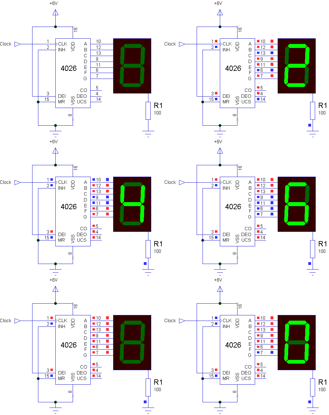
We have discussed the simple 4026 manual Digital Counter circuit with reset and pause options. In this led 7-segment display counter circuit we are using a single digital counter IC (4026) both as a counter and 7-segment driver. A common cathode 7-segment display is used here. The IC used here requires only clock pulses for operation. You can extend the counting limit up to infinity by increasing the number of ICs of this circuit. Even you can transform this digital counter circuit into a digital frequency counter circuit. Let’s learn in detail below.
4026 Digital Counter Circuit Diagram
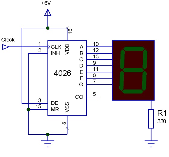
Components Required
- IC 4026
- 7 segment display
- Resistor 220 Ohm
- 6V power supply
Working Procedure of Digital Counter Circuit
- IC 4026 is basically a decade counter (10 States – counts 0 through 9). Also, it has an inbuilt 7-segment display driver which makes interfacing with 7-segment display easily.
- 4026 drives only common cathode seven-segment displays. As the name indicates a common cathode seven-segment display has its cathode shorted and grounded.
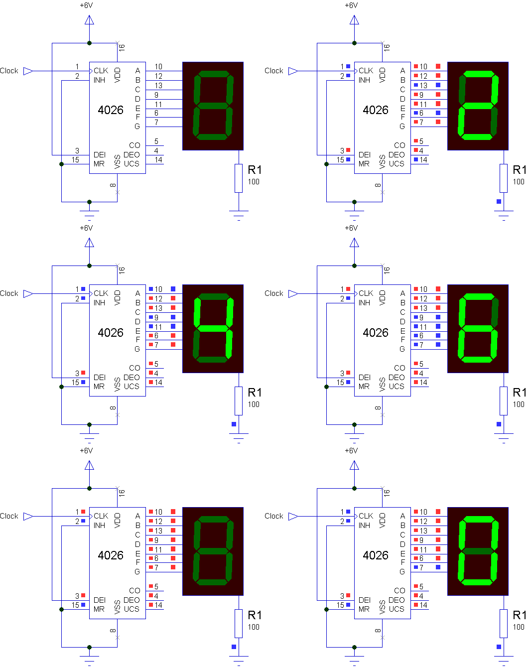
- Pin 1 is the Clock input and Pin 2 is the clock inhibit which is used for disabling the clock. It can be used to pause the counting when desired.
- Pin 15 (Master reset pin) helps to reset the counter. Pin 2 and 15 are active high, so we are grounding them to enable the counting process. They should be connected to Vcc for their respective actions.
- Pin 3 is the display enable pin which enables the display.
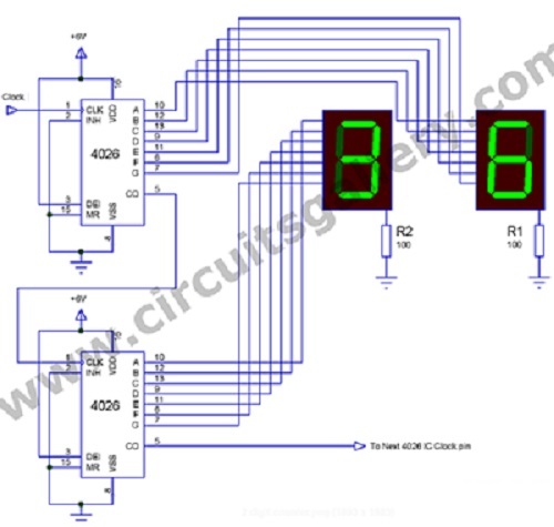
- Pin 5 is the carry output pin that generates a carry each time the count exceeds 9. It is used for extending the counting limit by connecting to the next IC’s clock pin.
- You can use a 555 astable multivibrator as the clock input.
- For 2-digit display digital counter circuits, 0 to 99 connect the carry out of the first IC as the clock of the 2nd IC as seen below. You can increase the digits as much as you want by repeating the process with more ICs and displays.
- Resistor R1 is used as a current-limiting resistor. You can vary the brightness of the display by varying the resistance value. But this brightness will not be uniform for each digit, Uniform brightness can be attained by connecting individual resistors for each anode segment.
Pin-out of 4026 Digital Counter IC and Display
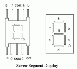
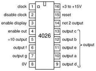
This manual digital counter circuit has a reset and pauses feature that is very crucial most of the time. The seven-segment display will show the count value and this small circuit could be a very important part of your project.
3. Ring Counter Circuit Working Principle with Animation and Video
Digital counters have several applications in electronic circuits and ring counter circuit is one of them. It is a register counter which is formed by feeding the output of a shift register to its own input. To help you make your own ring circuit, we are going to deliver the idea, working animation, and circuit simulation video of the ring counter circuit in this section.
Digital Counter Schematic Circuit
Components Required for Digital Electronics Counters
- Power supply
- IC 7474 x 4
- LEDs x 4
- Resistors 47kΩ x 4
- Clock circuit
Ring Counter State/ Truth Table
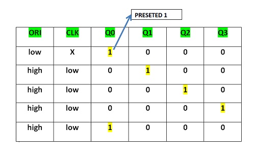
Working of Ring Counter Circuit
- This counter is a circulated shift register. Here a 4-bit shift register is implemented with 7474 flip flops. This is a synchronous counter because a clock signal is common for all flip-flops.
- The ‘Q’ output of the first flip-flop is directly fed to the ‘D’ input of the following flip-flop unit.
- The final ‘Q’ output from the last flip flop is connected to the ‘D’ input of the 1st unit; hence it is called a circulating shift register.
- The ‘Preset’ pin of the 1st unit is connected to Vcc via a switch (Push to OFF switch). A preset pin is used to set the output of a flip-flop to logical high (1) forcefully.
- The ‘Presets’ of other flip flops are directly coupled to Vcc in order to work properly because these pins are active low logic pins (This connection is not shown in the above circuit. For simplicity it is removed). But don’t forget to connect it while you are implementing it practically.
- Similarly ‘Clear’ pins are also connected to Vcc due to the above-said reason.
- We are already familiar with shift registers that for each clock pulse the data will be shifted to the next register (flip flop).
- Initially, all the outputs of flip flops are at low, to start the ring counter you need to set the output of the first flip flop manually high.
- For this purpose you just push the switch (SW2), then the output of the first flip-flop goes high.
- This output will be shifted to the next flip-flop during the next clock pulse and so on. At the same time, the low output from the last flip-flop is shifted to the input of 1st flip-flop.
- Please refer to the animation and video for a better understanding.
Ring Counter Circuit Animation
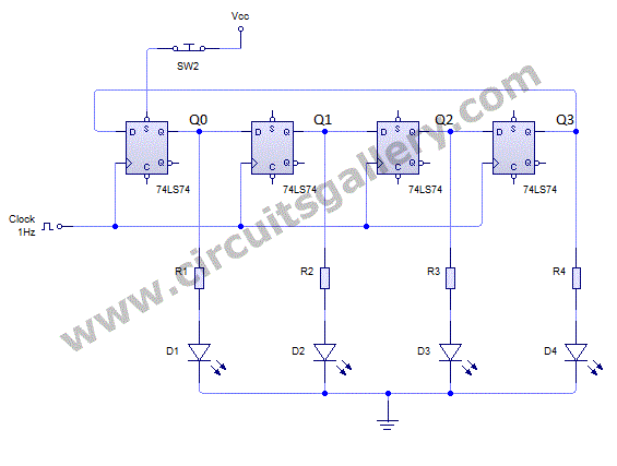
A ring counter is a very common and popular project nowadays for project showcasing or as part of an academic sessional. As all the step-by-step processes are discussed here, we hope now you can easily make your own ring counter circuit after following the above instructions.
4. Asynchronous Binary Up Counter Circuit With Working Procedure
Another famous digital counter circuit is the Asynchronous 4-bit binary up counter circuit. It is basically a digital counting circuit that counts up in an incremental mode. We are going to discuss this counter circuit along with the simple counting circuit setup using 4 flip-flops and also, and we have provided simulation videos so that you can learn about building this circuit more accurately. Let’s read the section below carefully if you want to build the Up Counter circuit.
Digital Logic Counter Circuit Schematics
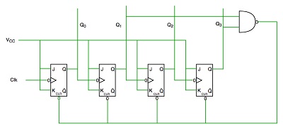
Components Required for Binary Up Counter Circuit Design
- Power supply
- 7473 JK flip flop IC x 2
- Resistors (1kΩ x 4)
- LEDs x 4
- 1Hz clock of 1Hz Astable multivibrator
Working Procedure of The Digital Logic Counter
- In this digital counter circuit setup, all flip-flops are clocked by the Q outputs of previous flip-flops. Thus, it is called an asynchronous counter.
- All the JK flip-flops hold their J and K inputs at logic ‘1’. 7473 IC is a dual JK master slave flips flop with a clear pin.
- A ripple counter comprising N flip-flops can be used to count up to 2N pulses. That is, a circuit with 4 flip-flops gives a maximum count of 24=16.
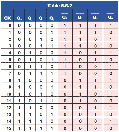
- This counter gives a natural binary count from 0 to 15 and resets to the initial condition on the 16th input pulse.
- Since J and K inputs of all the flip flops are connected to logic ‘1’, they act as a toggle flip flop.
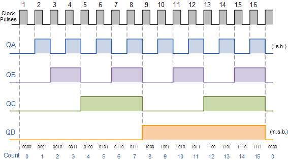
- Here the output of each flip flop toggles at the negative transition of clock input.
- With the application of 1st clock pulse, Q0 changes from 0 to 1, whereas Q1, Q2 and Q2 remains unaffected.
- On 2nd clock pulse Q0 becomes 0 and Q1 becomes 1. This process occurs for other flip flops also.
- If we are taking output from Q’, we will get a down counter simultaneously.
- You can use an astable multivibrator circuit for generating clock pulses.
Binary Up Counter Circuit Truth Table
0 to 15 binary counting sequence of Up Counter is shown below
Output Wave Form of Binary Up Counter
Status of each output in the counter is plotted on CRO Screen as
A binary up counter circuit has the potential to become the core counting unit of projects where critical counting is required. Whether it be a revolution counter or an enormous array arrangement, you’ll find a counter in it.
Conclusion
Among the synchronous digital counters, ring counters are well known and well-used and among the ring counters Johnson ring counter has a special space for its applications. Here we have discussed how you can build a manual digital counter using 4026 IC and have shown demonstrated videos and animations of making synchronous and asynchronous digital counter circuits such as ring counter, Johnson ring counter, and binary up counter circuits.
We believe you can now easily make your own simple digital counter circuit after reading this article. If you still have any confusion regarding this topic, feel free to ask in our comment section below, and we’ll try to reach you as soon as possible.
- 1. Johnson Digital Counter Circuit Diagram Using D Flip Flop 7474 (3 Bit/4 Bit) With Animation/ Simulation
- 2. Simple 4026 Manual Digital Counter Circuit With Reset and Pause
- 3. Ring Counter Circuit Working Principle with Animation and Video
- 4. Asynchronous Binary Up Counter Circuit With Working Procedure
- Conclusion
Subscribe to our newsletter
& plug into
the world of circuits