Doerr Electric Motor LR22132 Wiring Diagram: LR22132 Motor Wiring
Electric motors are the workhorses of modern industry, powering everything from household appliances to large machinery. Among the multitude of electric motor manufacturers, Doerr stands out for its reliability and efficiency. For anyone delving into the world of electrical appliances and motors, understanding the wiring diagram is crucial.
In this article, we will delve into the wiring diagram of the Doerr Electric Motor LR22132, providing an in-depth understanding of its components and connections.
How to Read the Wiring Diagram for a Doerr LR22132 Motor?
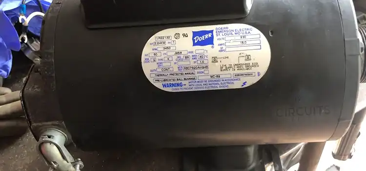
Doerr Electric, a renowned manufacturer in the industry, produces a wide range of electric motors known for their durability and high performance. The LR22132 model is one of their popular offerings, valued for its efficiency and versatility. To harness the full potential of this motor, understanding its wiring diagram is paramount. The main components that consist of the motor are given below,
- Power Supply: The Doerr Electric Motor LR22132 requires a 115-volt power supply to operate. It is important to ensure that the power supply matches the motor’s requirements.
- Start Capacitor: The start capacitor is responsible for providing the initial boost of power necessary to start the motor. It stores electrical energy and releases it during the motor’s startup phase.
- Run Capacitor: The run capacitor is used to maintain a steady flow of current to the motor during operation. It helps improve the motor’s efficiency and performance.
- Start Switch: The start switch is a crucial component that controls the flow of current during the motor’s startup. It is typically a mechanical switch that engages the start capacitor and disengages it once the motor reaches its operating speed.
- Centrifugal Switch: The centrifugal switch is another critical component of the Doerr Electric Motor LR22132. It is responsible for disconnecting the start winding from the circuit once the motor reaches its operating speed. This ensures that the start winding does not remain energized during normal operation.
Wiring Diagram Connections of LR22132 Motor
The following wiring diagram shows how to connect the LR22132 motor to a 230-volt power supply:
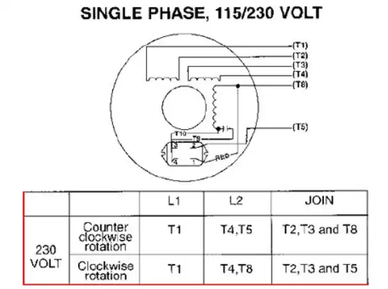
The wiring diagram shows the following terminals:
- T1: Line 1
- T4: Line 2
- T5: Capacitor start
- T8: Capacitor run
They are briefly explained below,
- Power Supply Connections: The motor’s power supply connections consist of two wires: a hot wire (usually black) and a neutral wire (usually white). These wires must be connected to the corresponding terminals on the motor.
- Capacitor Connections: The start capacitor and run capacitor have specific terminals on the motor where they should be connected. These terminals are labeled accordingly, and it is crucial to ensure correct connections to prevent motor damage or malfunction.
- Start Switch and Centrifugal Switch Connections: The start switch and centrifugal switch are typically wired in series with the start winding. These connections should be made according to the wiring diagram provided by the manufacturer.
Tips for Fixing Wiring Issues with a Doerr LR22132 Motor
Here are some troubleshooting tips:
- Refer to the Motor Manual or Diagram:
- Always start by referring to the motor manual or wiring diagram provided by the manufacturer. This document will typically include information about the proper connections for your specific motor model.
- Check Power Supply:
- Ensure that the power supply to the motor is correct. Verify the voltage and frequency match the motor’s specifications.
- Inspect Wiring Connections:
- Examine all wiring connections to ensure they match the diagram. Look for loose or disconnected wires.
- Verify Motor Rotation:
- Confirm the correct rotation direction of the motor. Incorrect rotation can sometimes be corrected by swapping any two of the three power leads.
- Check for Grounding:
- Ensure that the motor is properly grounded. A lack of grounding can lead to safety issues and operational problems.
- Inspect for Short Circuits:
- Check for any short circuits in the wiring. Insulation damage or exposed wires can cause short circuits and malfunction.
- Test Continuity:
- Use a multimeter to test the continuity of each wire. This helps identify any breaks or faults in the wiring.
- Verify Motor Temperature:
- Motors are designed to operate within a certain temperature range. If the motor is getting excessively hot, it may indicate a problem with the wiring or the motor itself.
- Check for Mechanical Issues:
- Inspect the motor for any mechanical issues, such as blocked or stiff bearings, which can affect performance.
- Consult Manufacturer Support:
- If you are unable to identify or resolve the issue, contact the manufacturer’s customer support for assistance. They may provide specific guidance based on the model and specifications of the LR22132 motor.
Safety Measures
Safety is paramount when dealing with electric motors. The wiring diagram aids in safe disconnection and reconnection of the motor, preventing accidents and ensuring the well-being of technicians and users.
Frequently Asked Questions
Which is the hot wire L1 or L2?
L1 and L2 are the wires which go to and from the power source. L1 is the hot wire. It carries 120V to the components. L2 is the neutral wire.
What do the wire colors signify in the Doerr LR22132 motor?
Black wires typically represent power supply, white wires indicate common terminals, and red wires are often used for high-speed settings.
Can I reverse the rotation direction of my Doerr LR22132 motor, and how is it done?
Yes, the rotation direction can be reversed by altering specific connections. Refer to the wiring diagram to identify the correct terminals to switch for reversing the motor.
To Conclude
Doerr Electric Motor LR22132 wiring diagram is crucial for both enthusiasts and professionals to make informed decisions about motor applications, repairs, and maintenance. It ensures safety and efficiency, and as technology advances, it enhances our capabilities and ensures seamless integration of electric motors into our interconnected world.
Subscribe to our newsletter
& plug into
the world of circuits