Fire Alarm Riser Diagram | Explained
Fire alarm systems are crucial life safety systems in modern buildings. A fire alarm system is a safety feature in buildings that detects fires early, alerts occupants, and notifies first responders.
At the heart of these complex systems are fire alarm riser diagrams. The riser diagrams utilize symbols, labels, and drawing conventions to depict the components and arrangement of a system. These diagrams provide a map of the components and wiring that make up the overall fire detection and notification system.
This article will provide a comprehensive overview of standard fire alarm riser diagrams.
Key Components of Fire Alarm System In A Riser Diagram
The system consists of various interlinked components, including:
1. Fire alarm control panel (FACP): The brains of the system that monitors all devices, trigger notifications, and communicates with first responders.
2. Remote Transponders: These field devices provide supplemental monitoring and control capabilities.
3. Initiating Devices: Connect to the FACP circuits to detect fires and signal the control panel. These include smoke detectors, heat detectors, manual pull stations, water flow switches, and duct detectors.
4. Notification Appliances: Connect to the control panel to alert building occupants of a fire emergency. These include horns, speakers, strobes, and combination speakers.
5. Power Supplies and Batteries: Power supplies provide electrical power to the various components of the fire alarm system. Batteries serve as backup power sources in case of a primary power failure, ensuring the system remains operational.
6. Circuits: Interconnect devices and transport signals. Signaling line circuits (SLC), notification appliance circuits (NAC), and auxiliary power circuits.
7. Zones: Larger systems divide the building into zones for selective evacuation and alarm source identification.
8. Interfaced Equipment: Equipment interfaced with the system, like HVAC and fire suppression systems.
Standard Rules Of Fire Alarm Riser Diagram
Riser diagrams follow standard conventions like:
Fire Alarm Riser Diagram Symbols
Riser diagrams use symbols, lines, and text formatting to represent the fire alarm system components:
Initiating devices are represented by symbols like:
- Circle: Smoke detector
- Diamond: Heat detector
- Square: Manual pull station
Notification appliances use symbols like:
- Rectangle: Horn
- Bell: Speaker
Lines connect devices to the FACP and each other. Styles indicate circuit type:
- Solid: Initiating device circuit
- Long dash: Notification appliance circuit
- Short dash: Low voltage communication link
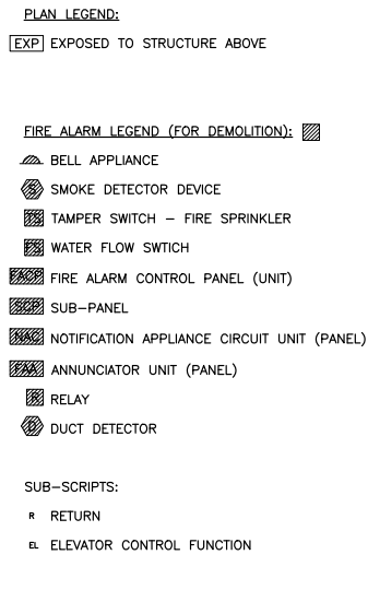
Fig. Legend and Symbols used in Riser Diagram.
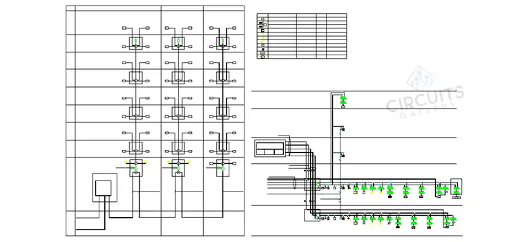
How to Read and Analyze a Fire Alarm Riser Diagram
Understanding the symbols and conventions we can now read a fire alarm riser diagram:
Frequently Asked Questions and Answers (FAQs)
What Is the Benefit of Having Standardized Fire Alarm Symbols?
Answer: Standardized symbols allow anyone to quickly interpret the diagram regardless of who drew it.
How to Use the Riser Diagram During Annual Fire Alarm Testing?
Answer: Use it to locate devices and zones. Check off each item as it is tested to ensure complete coverage.
Who Approves the Riser Diagram?
Answer: The local authority having jurisdiction reviews it for code compliance during permit approval.
To Conclude
Understanding fire alarm riser diagrams is crucial for anyone working with the systems. While complex, the symbols, zoning, and wiring make sense with study and practice. Imposing these diagrams to map out and troubleshoot connections saves time and avoids costly mistakes.
Subscribe to our newsletter
& plug into
the world of circuits