GE Dryer Motor Wiring Diagram – Detailed Guide
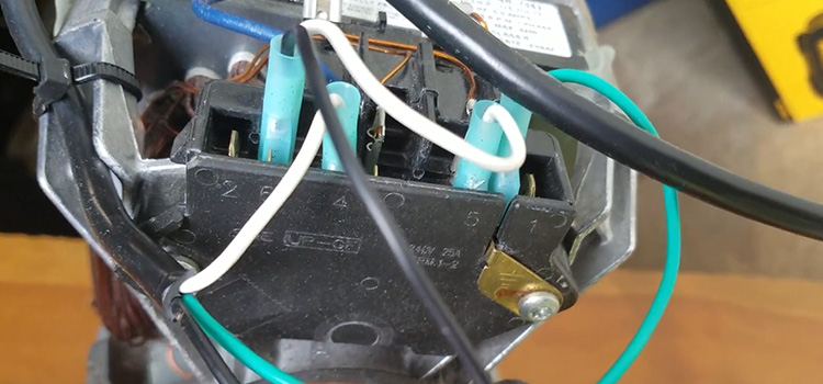
In the heater circuit, the two large wires are connected to a series switch. These wires can be used to turn on and off other devices. Centrifugal force is used to operate the switch. The switch also disconnects the start capacitor and powers the purple run winding wire.
Examine the wiring schematic for your dryer to see if the voltage is being delivered to the heating or motor circuits. The dryer motor generates the circular motion necessary to turn the dryer drum and blower. When necessary, the timer should allow energy to flow to the dryer’s heating element and motor.
GE Dryer Motor Wiring Diagram and Schematic
The field and the armature are linked in series Both have the same current flowing through them. They couldn’t possibly have two distinct wire sizes. The picture below shows the wiring diagrams of the GE dryer motor.
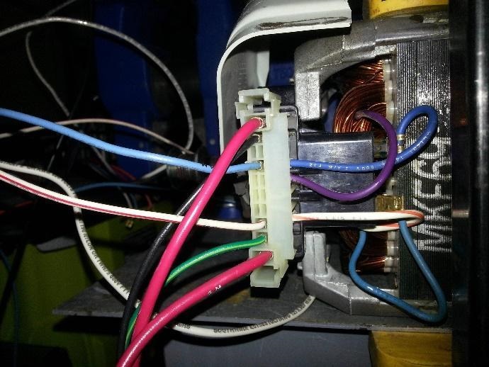
Figure 1: Wiring diagram of GE dryer motor
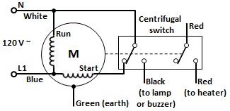
Figure 2: Schematic diagram of GE dryer motor
- The main winding, a start winding, and a centrifugal switch are inside a dryer motor.
- The black object is a microswitch (relay) that de-energizes the start winding when the motor reaches maximum speed.
- The red wires could be used to power the heating element.
How Do You Change a GE Dryer Motor Along With Wiring
All of the instructions for a GE dryer motor replacement are given below:
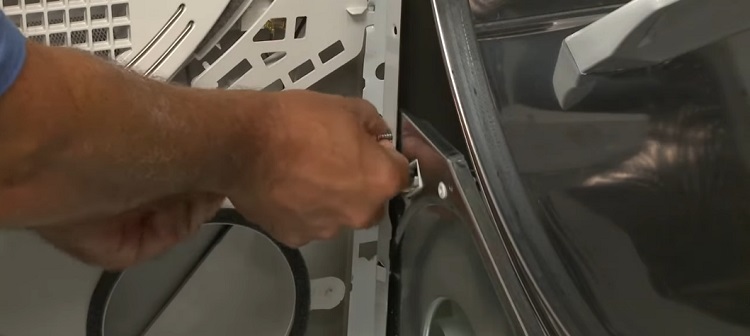
- Unplug the appliance before beginning. Remove the screws at the rear of the control panel and the screws inside the door frame. Now unhook the control panel tabs from the main top. Then remove the screws from the support panel as the following figure.
- Push the idler pulley to release the tension on the belt and unthread the belt from the pulley and rotor shaft as the following figure. Use the belt to lift the drum.
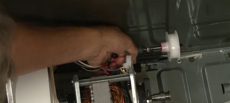
- Disconnect the motor wire harness as well as the belt switch wires. Also, disconnect the power chord connectors and the door wires and move the switch gear out of the way. Now disconnect the door switch wires and feed the wires through the support panel.
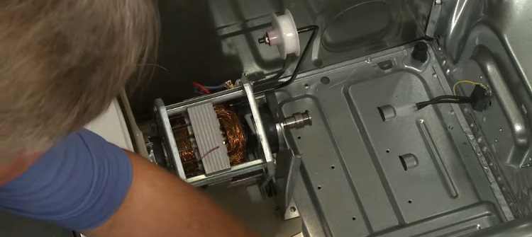
- Move the wires out of the way and slide the blower when and the motor assembly out of the housing. Now detach the idler arm and remove the blower wheel and motor from the cabinet. Perform the steps as shown in the figure below.
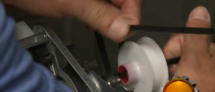
- To remove the blower wheel, use pliers to grip the motor shaft while rotating it counter-clockwise. This may necessitate some effort. Now, take the screws out of the front bracket. Remove the rear mounting clip with a flathead screwdriver. Take it off the mounting bracket.
- At this point, you are ready to install the new motor. Place the new motor correctly on the mounting bracket. Insert the rear mounting clip and tighten the screws in the front bracket. Thread the blower wheel clockwise onto the motor shaft to replace it.
- As you tighten the wheel, secure the shaft. Reattach the idler arm and slide the assembly back into the housing after returning the motor and blower wheel assembly to the cabinet. Return the wires to their original positions.
- Replace the screws that secure the assembly to the support panel and the mounting bracket. To secure the grounding wire, replace the screw. Attach the cycling thermostat to the blower housing using screws. Thread the wire harness for the door through the support panel.
- Reattach the cables and connector to the door switch. Connect the power cord connector once again. Reattach the belt switch and motor wiring harness. Align the drum shaft and bearing with the bearing retainer on the back panel to replace the drum in the cabinet.
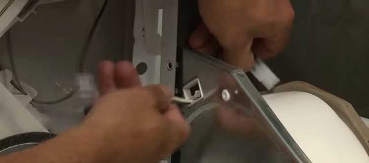
- Reach under the drum and thread the belt in a zig-zag pattern onto the pulley and motor shaft. Now, rotate the drum to assist the belt alignment. Replace the screw or screws that hold the cabinet sides to the support panel. Adjust the front panel by inserting the tabs first as the figure below.
- Lift the drum and secure the front panel in place. Screw the screws in place. Insert the control panel tabs into the slots at the back of the main top to replace them. Replace the screws after they have been fully positioned. The screws at the back secure the control panel.
- You can now reconnect the power cord and check that the appliance is working properly.
Frequently Asked Questions
Why Is GE Dryer Not Getting Power?
If the dryer is buzzing but not working, the drive motor should be checked. First, check to see if the drive belt has snapped, worn out, or simply slipped. If it appears to be in good condition, you may have a faulty drive motor that has to be replaced.
How Do I Test a GE Dryer Motor?
A test to verify if the motor is in good working order is to connect a test cord to terminals 4 and 5 on the motor and plug it into a 120-volt outlet to see if the motor will operate.
If the motor operates, the problem is somewhere else (for example, a possible open door switch, timer, or safety motor thermostat); if the motor remains dead with direct power to it, the motor is faulty.
Conclusion
Depending on the brand and model, a GE dryer motor costs between $250 and $450. Repair expenses are higher for more expensive motors used in premium washing brands. Most dryer problems can be fixed in an hour or less with a few essential tools and a continuity tester or multimeter.
Subscribe to our newsletter
& plug into
the world of circuits