GE Motor Wiring Diagram | A Comprehensive Guide
General Electric (GE) has had a solid reputation within the field of electrical engineering for more than a century. Due to their constancy and efficiency, GE motors are frequently utilized in both industrial and domestic settings. To ensure proper operation, it is essential to comprehend the wiring diagrams for these motors.
In this article, we’ll see GE motor wiring diagrams and give you a detailed breakdown of its meaning.
Key Components in Motor Wiring Diagrams
Certainly, here’s a bit more detail on each of the key components in motor wiring diagrams –
1. Power Source
The voltage level (e.g., 120V, 240V) and frequency (e.g., 50Hz, 60Hz) of the electrical supply are all depicted in this component. This energy source drives the motor.
2. Motor
The main element responsible for performing mechanical labor is the motor. Its type (such as induction or synchronous) and power rating (voltage, current, and horsepower) serve as identifiers.
3. Terminals
Motor terminals are the areas at which electrical connections are made. They are frequently given numbers or letters in order to recognize each terminal and ensure proper wiring.
4. Windings
A few motors, including single-phase induction motors, have independent starting and running windings. These windings are recognized, and their connections are shown, guaranteeing suitable operation.
5. Capacitor
When utilized in single-phase induction motors, capacitors improve the motor’s startup and operation. The diagram shows the type of capacitor, its size, and how it is connected to the motor.
6. Devices for Control
These components, which incorporate switches, relays, contactors, and pushbuttons, regulate the motor’s action in a variety of ways, including starting, stopping, and reversing.
7. Overload Prevention
To prevent the motor from overheating, thermal overload prevention measures are integrated into the design. They are frequently connected in series with the engine and act as security highlights.
8. Reversing switch
The diagram shows how to connect reversing switches so that a motor (for reversible motors, for example) can alter the direction in which it rotates.
9. Grounding
Proper grounding connections offer electrical security by preventing electrical shocks. Labels or symbols for grounding are used to designate the location of the ground wire on the motor.
10. Control Circuitry
More sophisticated motor systems may contain motion-controlling circuitry. This incorporates components that regulate the motor’s operation, including timers, interlocks, and other control systems.
It is crucial to comprehend these components while working with motors, whether during installation or troubleshooting, to ensure secure and efficient operation.
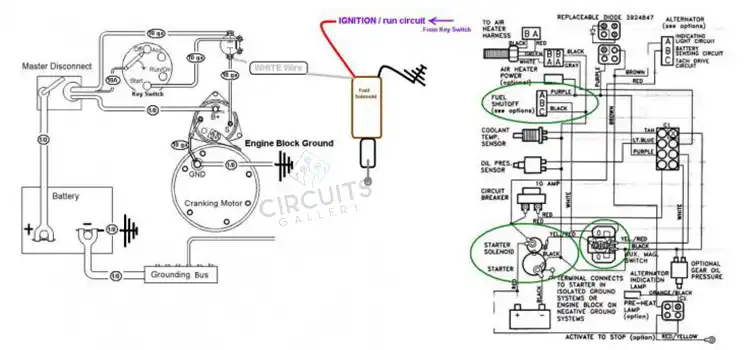
GE Motor Wiring Diagram
Image 1- GE Motor Wiring Diagram
Understanding the GE Motor Wiring Diagram
GE motor wiring schematics follow a common pattern even though they initially appear to be complicated. Here is a breakdown of the key components and symbols in these diagrams:
1. Motor Outline
The diagram shows a broad motor outline along with labels identifying the different parts and elements.
2. Wiring Color Codes
Different wire colors stand in for diverse functionalities. Common color-coding includes black, white, and green for hot (live) cables, neutral (white), and ground (green or bare copper) wires.
3. Lines and Arrows
Lines linking different components represent electrical connections. Arrows demonstrate the current flow’s direction.
4. Symbols
Components and connections are represented by symbols in wiring diagrams. Typical symbols consist of:
– Switches: Open or closed circuits are displayed.
– Relays: Represented as rectangular objects with power and control terminals.
– Capacitors: Shown as a pair of parallel lines.
– Motors: Depicted as circular or oval shapes.
– Transformers: Displayed as two coils connected at the center.
5. Numbers and Labels
Typically, components are designated by numbers or letters that match a legend or key that depicts each component’s purpose in further detail.
Frequently Asked Questions and Answers
What are the common types of GE Motor Wiring Diagrams?
Diagrams for single-phase and three-phase motors, motors with capacitors, reversible motor diagrams, and motor diagrams with different control options are a few examples of typical types.
How can I troubleshoot problems with a GE motor using the wiring diagram?
The wiring diagram is a basic tool for troubleshooting and can assist you in finding potential motor problem reasons, such as defective components, weak connections, damaged wires, or improper wiring.
Can I modify a GE Motor Wiring Diagram to fit my specific application?
Even if a few little adjustments might be possible, an authorized electrician or engineer should be consulted before making any wiring diagram changes. When making alterations, safety guidelines and electrical rules must be obeyed.
Conclusion
For secure installation, reliable operation, and efficient troubleshooting of GE electric motors, GE motor wiring diagrams are fundamental. For a motor to function reliably, one must be able to comprehend symbols, parts, and linkages. Safety must always come first; for difficult actions, seek professional guidance.
Subscribe to our newsletter
& plug into
the world of circuits