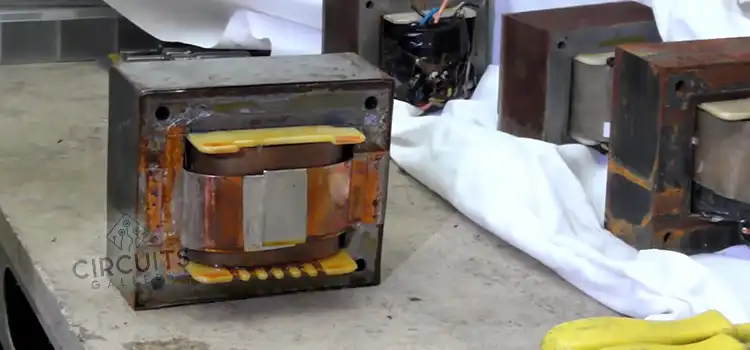
How Much Copper is in A Transformer? | Understanding Copper Usage in Transformers
Isn’t it an interesting thing that a transformer contains copper? The amount of copper in a transformer can vary widely depending on the transformer’s size, design, and purpose. In this article, we will talk about the existence of copper in transformers and its importance.

Why Copper is Used in a Transformer?
Copper is utilized in transformers for its excellent electrical conductivity and suitability as a conductor. This ensures efficient energy transfer with minimal losses. Its low resistance minimizes heat generation during operation, optimizing performance and durability.
Copper’s high current-carrying capacity suits transformers handling substantial loads, while its mechanical properties aid in winding creation. Corrosion resistance and long-term reliability further enhance its appeal.
Ultimately, copper’s exceptional attributes make it an ideal material for transformer windings, contributing to effective energy distribution, reduced wastage, and reliable power transmission.
What are the Factors that Affect the Amount of Copper in Transformer?
The following factors can influence the amount of copper used in transformers:
- Power Rating and Size: Larger transformers handling higher power levels generally require more copper due to the increased current flowing through the windings.
- Efficiency Requirements: Higher efficiency goals may necessitate larger copper cross-sectional areas to reduce resistive losses.
- Load Variability: Transformers subject to varying loads may need more copper to handle the associated currents without excessive losses.
- Voltage Levels: Transformers stepping voltage up or down impacts the number of turns in the windings and, subsequently, the amount of copper needed.
- Design Topology: Different transformer topologies (core type, shell type, etc.) affect how windings are configured and the copper they use.
- Material Costs: Copper prices influence design decisions; cost-effective designs aim to balance copper usage and performance.
How to Calculate the Weight of Copper in a Transformer?
To calculate the weight of copper in a transformer, you need to consider the dimensions of the copper windings, the cross-sectional area of the copper wire used, and the length of the wire in each winding. Here’s a step-by-step process with an example:
Let’s assume the following specifications:
Primary winding: 500 turns of copper wire with a diameter of 1.5 mm
Secondary winding: 1000 turns of copper wire with a diameter of 1.0 mm
Length of each winding: 50 meters
Density of copper: 8.96 g/cm³
Calculation:
Firstly, calculating cross-sectional Area:
Primary winding: radius = 1.5 mm / 2 = 0.75 mm = 0.0075 cm
Primary winding cross-sectional area = π * (0.0075 cm)² = 0.00017671 cm²
Secondary winding: radius = 1.0 mm / 2 = 0.5 mm = 0.005 cm
Secondary winding cross-sectional area = π * (0.005 cm)² = 0.00007854 cm²
So, the length of each winding = 50 metres = 5000 cm
Now, calculate the volume of copper:
Primary winding volume = Primary winding cross-sectional area * Length
= 0.00017671 cm² * 5000 cm
= 0.88355 cm³
Secondary winding volume = Secondary winding cross-sectional area * Length
= 0.00007854 cm² * 5000 cm
= 0.3927 cm³
Again, calculating the weight of copper:
Weight of copper in primary winding = Primary winding volume * Density
= 0.88355 cm³ * 8.96 g/cm³
= 7.9153 grams
Weight of copper in secondary winding = Secondary winding volume * Density
= 0.3927 cm³ * 8.96 g/cm³
= 3.517 grams
Finally, the Total weight of copper:
Total weight of copper in the transformer = Weight of copper in primary winding + Weight of copper in secondary winding
Total weight of copper = 7.9153 grams + 3.517 grams = 11.4323 grams
Types Of Copper Used in Transformer
Electrolytic Tough Pitch (ETP) copper is used in transformers because of its balanced conductivity and cost-effectiveness. With less oxygen than regular copper, oxygen-free copper (OFC) delivers improved conductivity for applications that demand top-notch performance.
High-performance transformers benefit from the conductivity and thermal properties of copper that contains silver. Special needs are met by copper alloys like copper-silver. While copper is the norm, aluminum is employed in areas where cost is an issue because it is less expensive.
Designers of transformers choose copper kinds depending on efficiency, performance requirements, and cost considerations, tailoring their selection to meet various electrical needs.
Frequently Asked Questions and Answers
1. How much copper weight is in a 500 kVA transformer?
The amount of copper in a 500 KVA transformer is typically 10-15% of the total weight of the transformer.
2. How heavy is a transformer in KG?
Large-sized transformers can weigh from 20,000 kg to over 100,000 kg or more. Whereas medium-sized transformers are between 1,000 to 10,000 kg. And small-sized transformers can weigh around 100-500 kg. The weight can vary according to its design, rating, and application.
3. Why is a transformer called kVA?
kVA is a unit to measure apparent power in electrical systems. It stands for kilovolt-amperes. kVA expresses transformers’ capacity which indicates their ability to handle electrical loads while changing voltage levels.
Conclusion
Copper has some unique characteristics like superior electrical conductivity, low resistance, great current-carrying ability, etc. Hence it has become a key component in building transformers. The usage of copper ensures the proper functioning and performance of transformers in power distribution.
Subscribe to our newsletter
& plug into
the world of circuits