How to Calibrate an Oscilloscope | A Step-by-Step Guide
One of the most difficult techniques to learn is oscilloscope calibration. Getting things perfect might take a lot of time and work. However, if you follow some instructions, you will be able to calibrate your scope more quickly and successfully.
Using the oscilloscope’s built-in reference point or having it professionally calibrated is the one correct way to go. The proper calibration of an oscilloscope necessitates the use of a calibration handbook, calibrated standards to measure with, tools and software to calibrate the scope, and so on.
Steps for Calibrating an Oscilloscope Accurately
Oscilloscopes are used to measure electronic signals. These devices produce a waveform, which is a curve that represents an electric signal for a certain voltage or power source. You should calibrate the oscilloscope with a known amount of controlled values before using it to conduct measurements.
This ensures that your specifications are met to scientific and engineering standards. The steps for calibrating the oscilloscope are outlined below. Remember that each oscilloscope may differ, and the controls on different models may have different names.
Step 1: Examine the Controls
Examine all of your scope’s controls and return them to their original places. All rotating dials should be aligned, all pushbuttons should be out, and all slide and paddle switches should be up on most scopes.
Step 2: Turn on the Scope
Give your oscilloscope a minute or two to warm up if it’s an old-fashioned CRT.
Step 3: Set the Volts/Div Control to 1
The scope is now adjusted to show one volt per vertical division. You may need to adjust this number depending on the signal you’re displaying, but one volt is a decent starting point.
Step 4: Set the Time/Div Control to 1 ms
The time interval indicated by each horizontal division on the display is determined by this control. Turn this dial to the slowest setting. Then, one notch at a time, increase the pace of the dot until it becomes a solid line.
Step 5: Set the Trigger Switch to Auto
The oscilloscope’s Auto position allows it to steady the trace on a common waveform trigger point. The waveform may wander across the screen if the trigger mode isn’t set to Auto, making it difficult to see.
Step 6: Connect a Probe to the Input Connector
Connect the probe to the input connector on your scope if it has more than one. Oscilloscope probes have a probe point and a separate ground line that you attach to the input signal.
An alligator clip is commonly found on the ground lead. This clip can be linked to any common ground point within the circuit while testing it. The ground lead on some probes is detachable, allowing you to remove it when not in use.
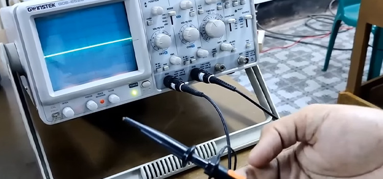
Step 7: Touch the End of the Probe to the Scope’s Calibration Terminal
The sample square wave provided by this terminal can be used to calibrate the scope’s display. Two calibration connections labeled 0.2 V and 2 V, are found on some scopes. Touch the probe to the 2 V terminal on your scope if it has two.
It’s best to calibrate with an alligator clip test probe. If your test probe has a pointed tip rather than an alligator clip, you can usually hold it in place by pushing the tip through the little hole at the end of the calibration terminal. The ground lead of your test probe does not need to be connected for calibration.
Step 8: Do the Necessary Adjustments
Adjust the TIME/DIV and VOLTS/DIV parameters as needed until the square wave fits well in the display. Adjust the Y-POS control to center the trace vertically if necessary. Adjust the X-POS control to orient the trace horizontally if necessary. Finally, adjust the Intensity and Focus settings as needed to create a clear trace.
How Do You Calibrate an Oscilloscope Probe?
To calibrate the oscilloscope’s probe go to the channel menu and seek the probe calibration button. You can walk through the amplitude and skew calibrations in less than 5 seconds each. The scope prompts you when the calibration is done.
Why Is It Important to Properly Calibrate Oscilloscope Before Its Usage?
An oscilloscope’s calibration is critically crucial. This is due to the fact that oscilloscope calibration aids in job integrity. Oscilloscopes must be able to read data reliably. When an oscilloscope is out of tolerance, the chances of making a mistake are significant.
False information causes you to waste more money on repair components and costly upkeep, as well as prolonging your investigation. Calibration should be done on a regular basis.
How Often Do Oscilloscopes Need to Be Calibrated?
The duration varies with different oscilloscopes. Though the variation is not highly significant. For most Keysight oscilloscopes, a 12-month calibration interval is suggested. However, you’ll need to assess your testing environment as well as your accuracy requirements to see if the typical interval is appropriate for your needs.
Many factors can have an impact on test equipment’s long-term accuracy. Temperature changes, high humidity, dust, and vibration can reduce an instrument’s accuracy and decrease its calibration cycle.
Do You Need to Calibrate Oscilloscope?
Yes, calibrating oscilloscopes is very important to get the accurate output. An oscilloscope must be calibrated because it is a precise instrument used to measure time, voltage, and a variety of derived quantities. Calibration ensures that voltage and time data can be traced back to a standard and that your results are reliable.
Conclusion
The majority of clients purchase an oscilloscope for its accuracy. The process of calibrating an oscilloscope includes some complexities. So it’s often suggested to seek help from professionals. However, if you go for yourself, read the owner’s instructions to determine if there are any extra setup or calibration processes you need to follow.
Subscribe to our newsletter
& plug into
the world of circuits