How to Connect Stranded Wire to Solid Wire | A Quick Guide for You
To connect stranded wire to solid wire, use wire connectors or wire nuts designed for this specific purpose. Strip a portion of insulation from both wires, insert the stripped ends into the connector, and twist it clockwise until secured tightly.
Another method involves using crimp sleeves or butt connectors. Strip the wires, insert them into the connector, and use a crimping tool to compress them tightly. Always verify the connection’s security by gently tugging the cables.
Can I Pigtail Stranded Wire to Solid Wire?
Pigtailing refers to the process of joining multiple wires together using a short length of wire. It is a commonly used technique for connecting stranded wire to solid wire. To pigtail stranded wire to solid wire, you will need a suitable connector, such as a wire nut or a crimp connector.
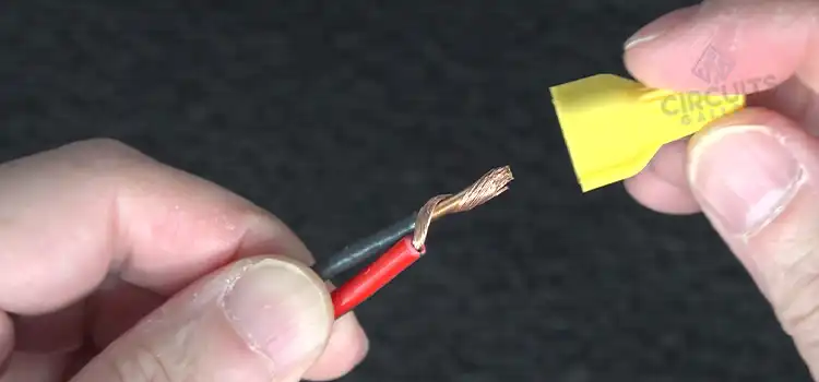
Steps to Pigtail Stranded Wire to Solid Wire
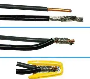
Figure 1: Pigtailing stranded wire to the solid wire
Follow the manufacturer’s instructions for the specific connector you are using to ensure a proper and reliable connection.
Can You Connect a Stranded Wire to a Solid Wire with a Wire Nut?
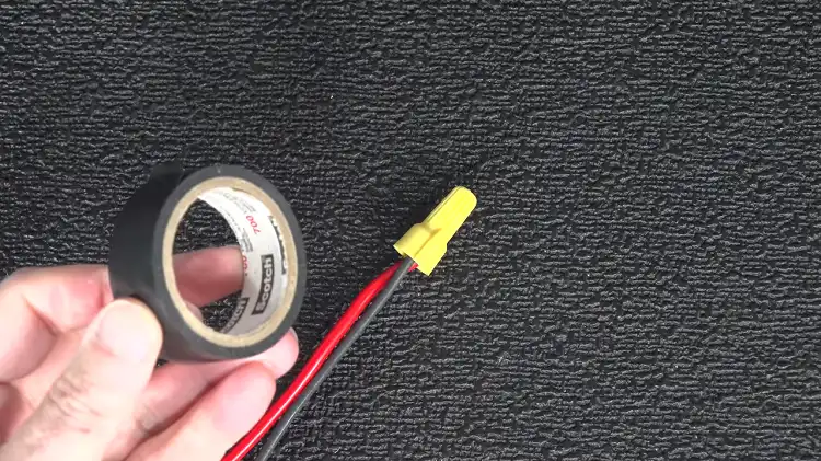
Figure 2: Connecting a stranded wire to a solid wire with a wire nut
Yes, connecting a stranded wire to a solid wire using a wire nut is possible. Wire nuts are commonly used to join and secure electrical wires together. They are designed to work with both stranded and solid wires.
Procedure to Connect Solid and Stranded Wires with Wire Nuts
1. Strip the insulation from both the solid and stranded wires, ensuring that the exposed stranded wire is longer than the exposed solid wire.
2. Next, place the wires together, wrapping the stranded wire around the solid wire.
3. Twist a wire nut over the twisted wires, making sure to fasten it securely. Ensure that the wire nut is properly sized for the wires being joined and features an internal metal spring.
4. Perform a pull test on the stranded wire and wire nut to ensure they are tightly secured and do not come loose.
Make sure to use insulating tapes after connecting to ensure a secure connection.
Can You Crimp Solid Wire to Stranded Wire?
Yes, it is possible to crimp solid wire to stranded wire using appropriate crimping techniques and tools. Here are the step-by-step guides to crimping solid wire to stranded wire:
Gather the Necessary Tools and Materials

Figure 3: A Crimping Tool
You will need a wire stripper, crimping tool, appropriate crimp connectors (such as butt connectors or splices), solid wire, and stranded wire.
Step 1: Prepare the Wires
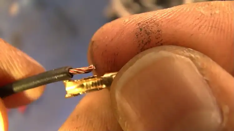
Figure 4: Stripping the insulation from the wires
Strip the insulation from both the solid wire and the stranded wire using a wire stripper. Make sure to remove the appropriate length of insulation from both wires, exposing the bare copper conductors.
Step 2: Insert the Wires Into the Crimp Connector
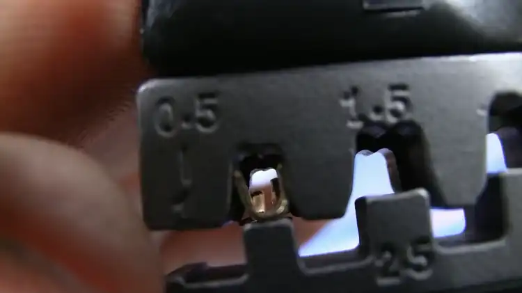
Figure 5: Insert the sections into the crimp connector
Get the stripped ends of the solid wire and the stranded wire and insert them into the desired sections of the crimp connector. The solid wire should be inserted into the section designed for solid wire, and insert the stranded wire into the section for stranded wire.
Step 3: Position the Wires Correctly
Ensure that the bare copper conductors of both wires are fully inserted into the crimp connector. The conductors should be aligned properly, and make sure there are no overlaps or gaps.
Step 4: Crimp the Connector
Place the crimp connector into the appropriate slot in the crimping tool. Apply firm and even pressure to the crimping tool handles to crimp the connector onto the wires. Make sure to follow the instructions provided with the specific crimping tool you are using to ensure a proper crimp.
Step 5: Inspect the Crimp
After crimping, visually inspect the connector to ensure it is securely attached to both the solid and stranded wires. Check for any signs of incomplete crimpings, such as loose wires or an improperly formed crimp. If the crimp appears faulty, repeat the crimping process with a new connector.
Step 6: Test the Connection
Once you have crimped the wires together, it is recommended to test the connection for continuity or perform a pull test to ensure the crimp is secure and the wires are properly joined.
It’s important to note that using the correct crimp connectors designed for solid-to-stranded wire connections is crucial for achieving a reliable and secure connection.
To Conclude
In conclusion, it is crucial to use appropriate techniques and connectors while connecting stranded wires to solid wires. Whether using wire nuts or crimp connectors, always ensure that you are using the right type of connector for the specific wire types you are working with.
Subscribe to our newsletter
& plug into
the world of circuits