How to Find Threshold Voltage of a MOSFET From Graph? – Procedure to Follow
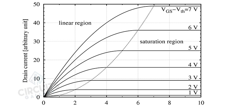
To determine the threshold voltage, use the equation of the drain current as a function of the gate to source voltage VGS in the VDS saturation region. VDS(sat)=> VGS-Vth defines the saturation region. The transfer curve at drain current saturation is what it is called.
Threshold voltage can be defined in a variety of ways for measurement purposes. One common metric is: Threshold voltage is the voltage at which the Ids (drain-source current) of a diode-connected MOS is 100nA. Other standard methods include the maximum slope method, the three-point method, and so on.
How to Determine the Threshold Voltage of a MOSFET through Graph Analysis?
As shown in the figure below, the threshold voltage deviates even further from the ideal scaling behavior than the power supply voltage. The gate voltage at which significant current begins to flow from the source to the drain is referred to as the MOSFET threshold voltage.
The current does not immediately cease to exist when the threshold voltage is reached. It instead decreases exponentially with a slope on the logarithmic scale that is inversely proportional to the thermal energy kT.
What Is the Equation of Threshold Voltage in MOSFET?
The threshold voltage is equal to the sum of the flat band voltage, twice the bulk potential, and the depletion layer charge voltage across the oxide, or:

where the flat band voltage, V(FB), is given by:

With,
And,

The following equations are used to calculate the threshold voltage of a p-type MOSFET with an n-type substrate:


How Do You Find the Threshold Voltage of a Diode From a Graph?
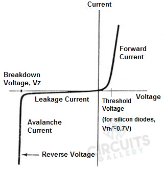
For current to flow, a minimum threshold voltage (or Vth, usually around 0.7V) must be present between the anode and cathode. No current will flow through the diode if the anode voltage is not at least Vth greater than the cathode voltage. The following graph shows the threshold voltage of a diode:
How Do You Find the Voltage of a Mosfet
To implement the voltage measurement of a MOSFET you’ll need the following equipment:
- Functional power supply
- A standard set of test equipment including a Variac
- Programmable AC source
- Digital multimeters (DMMs)
- Electronic load
- Oscilloscope
- Wattmeter and AC/DC probes
Now perform the following steps:
Selecting a Current Probe
- Begin the drain current measurement process by inserting a wire loop into the circuit to place the current probe.
- Now insert the loop into the circuit so that it only receives drain current.
- Then connect the current probe to the oscilloscope next. Set the bandwidth on the scope input to 20 MHz or higher if it is user selectable.
Voltage Measurement
- Start the voltage measurement process by going over the equipment requirements. A 100x voltage probe rated for at least 1000 V is required to measure switching voltage across the MOSFET.
- Both the scope and probe used to view the drain voltage waveform should have a bandwidth of 100 MHz or higher.
- Before connecting a probe to a circuit, it is critical to check its compensation.
- Connect the voltage probe to the scope first.
- Connect the probe to the scope’s compensation terminal and adjust the scope’s voltage and time base settings so that the test signal’s rising and falling edges fill the screen.
- Then, using the probe’s non-metallic adjustment tool, adjust the compensation capacitor until any waveform undershoot or overshoot is minimized.
How Is Gate Threshold Voltage Calculated?
Use a curve tracer to calculate the gate threshold voltage. The lowest VGS at which a specified small amount of ID flows is referred to as the gate threshold voltage. The test is carried out with VGS = VDS. The collector supply provides VDS on the curve tracer.
Patch cords connect the gate to the drain, resulting in VGS=VDS. The horizontal axis of the display shows VGS, and the vertical axis displays the resulting ID. When VGS is within the min/max limits at the specified ID, the specification is met.
Conclusion
The threshold voltage value can be extracted from measured drain current or capacitance characteristics using single or multiple transistors. This is the most important electrical parameter in modeling MOSFETs Practical circuits are also available to measure the threshold voltage automatically and quickly.
Subscribe to our newsletter
& plug into
the world of circuits