How to Find VPP on Oscilloscope? A Step by Step Guide
Adjust the vertical sensitivity of the oscilloscope while the waveform is displayed on the screen to get the figure as inclusive as possible without losing any from the top or bottom. Count the number of horizontal graticules on the screen from the bottom of the figure to the top of the figure. Multiply that amount by the sensitivity level that has been set.
What Does VPP Mean on an Oscilloscope?
Peak-to-peak voltage (Vpp) can be explained in terms of a sinusoidal-waveform voltage. It is a parameter measured between the maximum signal amplitude value and its minimum value which can be negative, over a single period. With a maximum value of 5 V and a minimum value of -5 V, the peak-to-peak voltage is 10 V.
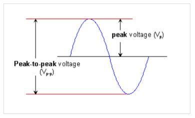
A similar parameter used in electronics is often mistaken for the peak-to-peak voltage, that is peak voltage denoted as Vp. Peak voltage (Vp) is measured from 0 to the maximum value (5V in the example). For a sinusoidal-waveform signal, Vpp will always be twice the Vp.
Steps to Find VPP on Oscilloscope
Using an Oscilloscope to measure peak-to-peak voltage is simple. The steps for measuring Vpp on an oscilloscope are given below.
Step 1: Do the Adjustments
Adjust the vertical location and sensitivity for the biggest display of the signal’s vertical height, so that both the upper and lower sections of the signal are seen on
the screen at the same time. Only use the ‘scope’s fixed vertical sensitivity settings.
Step 2: Measure the Vertical Distance
Find the maximum distance in cm between the highest and lowest signal levels.
Step 3: Calculate the Peak Voltage
The p-p voltage is calculated by multiplying the measurement from step two by the vertical sensitivity setting of the ‘scope.
How Do You Calculate Peak to Peak Amplitude From Oscilloscope?
First, make sure that the probe attenuation on the scope is set correctly for the probe you’re using. Also, ensure the signal is triggered correctly and is stable. Adjust the vertical scale to use as much of the display as you can without clipping the top and bottom. Set the horizontal scale to expand the part of the signal you’re interested in.
Be careful not to slow down the horizontal scale too much as this can under-sampling. The simplest way to get a quick estimation of amplitude measurement is by using the graticule or grid on the scope’s display.
The graticule is just a type of grid. Most oscilloscope graticule has 10 horizontal divisions and 8 or 10 vertical divisions. Each major decision is divided into 5 minor divisions.
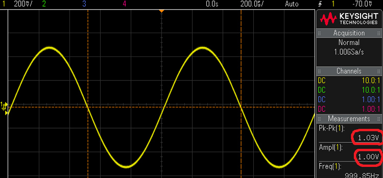
Peak to Peak Amplitude Measurement
Count the number of vertical divisions for amplitude measurement occupied by the signal’s vertical swing. Then multiply by the vertical scale. Measure the peak-to-peak voltage of the signal. To make the count easier, shift the waveform using the vertical position knob to line it up on the bottom of one of the grids.
Now find the height in divisions. Let’s say the signal takes up four major divisions and two minor divisions. Each minor division is worth point two divisions. So the signal will be 4.4 divisions from top to bottom.
You can see the vertical scale for the selected channel at the bottom left corner of the scope. If the voltage shown there is set to 1V per division, the peak-to-peak amplitude of the signal will be 4.4 div x 1V/ div= 4.4 volts.
Is Vpp the Same as Amplitude
For a sine wave, Amplitude is the fluctuation or displacement of the wave from its mean value. Peak-to-peak (pk-pk) is the difference between the maximum positive and the maximum negative amplitudes of the wave.
The pk-pk amplitude of an alternating current (AC) wave in the absence of a direct current (DC) component is twice the positive peak amplitude. When there is no DC component in an AC sine wave, the pk-pk amplitude is about 2.828 times the root-mean-square amplitude.
Conclusion
Oscilloscopes are one of the most important devices in electronics. It is very much needed to measure and analyze a signal’s waveform. To measure the peak-to-peak voltage and amplitude of a signal on an oscilloscope, you need to look over the display of the scope closely and follow simple steps.
Subscribe to our newsletter
& plug into
the world of circuits