How to Ground a Subpanel in a Detached Building? | A Step-by-Step Guide for You
To ground a subpanel in a detached building, pull 4 conductors and separate the grounded and grounding bus. This part is covered by National Electrical Code article 250.32, although it is one of the longest and most complicated portions in the whole grounding chapter, and it may be quite difficult.
According to the National Electrical Code, both subpanels and main panels must follow specific standards (NEC). A detached structure with a sub-panel requires its own ground rod, whether it is fed by three or four wires.

Procedure to Ground Your Outbuilding’s Power
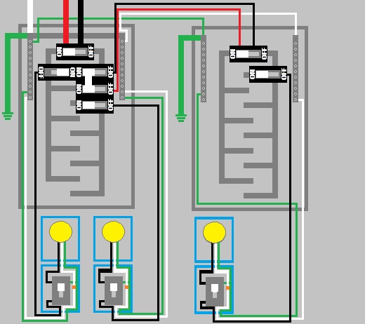
Pull four conductors: two ungrounded (hot), one grounded (neutral), and one grounding. At the sub-panel, the grounded (neutral) and grounding buses must be disconnected. Unless your local code permits it, there is no need for a GFCI breaker on the main panel. At the second structure, a grounding electrode system is necessary.

What Affects Grounding a Subpanel?
If any of the grounding electrodes listed in 250.52(A) are present at the building or structure being served, they must be connected together to form a grounding electrode system.
If there is no grounding electrode, one must be placed. A building or structure that is served by a single branch circuit, either individual or multiwire, that contains an equipment grounding conductor is exempt from the grounding electrode requirement in 250.32(A).
What are the Reason Behind the Separation of Grounds and Neutrals?
Current can travel on both ground and neutral back to the main panel when ground and neutral are linked. If the load becomes imbalanced and ground and neutral are bonded, current will flow through everything bonded to the sub-panel (enclosure, ground wire, pipe, and so on) and back to the main panel which is hazardous.
Specific Considerations
A feeder or branch circuit servicing a separate building or structure must normally have an equipment grounding conductor, according to NEC Article 250.32(B)(1). The EGC might be a wire or any of the wiring methods specified in section 250.118 that qualifies as an EGC. If it is wire, it must be sized according to 250.122.
Exception number one enables the grounded conductor of feeders or branch circuits to be utilized for grounding at different buildings or structures. An EGC is not included in the circuit that powers the distinct building. Second, no continuous metallic routes connect the feeder source to the destination at the building.
Grounding System for a Separate Structure
There is no need for a ground wire in the cable that feeds electricity to the panel at the separate structure. A GES, or Grounding Electrode System, must be installed at the subpanel’s distinct structure. The remote panel’s grounding electrode conductors must be sized in accordance with the NEC 250.66 Table.
Because the detached building has a ground system, the ground and neutral must be linked together at the panel. According to article 225.31 of the NEC, If there are more than six circuit breakers in the subpanel, the main breaker must be placed.
Necessary Materials and Tools
Collect the following materials and tools to complete the job:
Step-by-Step Guide to Ground a Subpanel in a Detached Building
Grounding a subpanel in a detached building is a crucial safety measure that ensures electrical systems function properly and minimizes the risk of electrical hazards. Here’s a step-by-step guide to help you with this process:
Step 1: Determine Subpanel Location
Choose an appropriate location for the subpanel. It should be easily accessible, well-ventilated, and away from water sources. Make sure it’s installed on a sturdy, fire-resistant surface.
Step 2: Install the Subpanel
Mount the subpanel to the wall according to the manufacturer’s instructions. Connect the hot and neutral wires from the main panel to the corresponding terminals in the subpanel. Ensure these wires are the appropriate gauge for the amperage of the subpanel.
Step 3: Install Grounding Electrodes
To ground the subpanel, you’ll need grounding electrodes, typically in the form of ground rods. Here’s how to install them:
Step 4: Connect Grounding Electrodes
Connect a length of copper grounding wire (at least 6 AWG) to the ground rod using a grounding clamp. Run this wire from the first grounding rod to the subpanel. Repeat this process for the second grounding rod if required by local code.
Step 5: Bond Ground Wire to the Subpanel
Inside the subpanel, bond the grounding wire to the grounding bar. This is typically a separate bar designed for grounding. Attach the wire securely using a grounding lug.
Step 6: Ground the Subpanel’s Circuits
Each circuit in the subpanel should be grounded to the grounding bar within the subpanel. This provides a path for fault currents to travel safely to the grounding system.
Step 7: Check and Secure All Connections
Double-check all connections to ensure they are tight and secure. Loose connections can lead to electrical problems and safety hazards.
Step 8: Test the Grounding System
After completing the installation, it’s essential to test the grounding system to ensure it functions correctly. This may involve using a ground impedance tester to check the resistance of the grounding electrodes.
People Also Asked (PAA)
How high off the ground does a sub-panel have to be?
All electrical panels should have at least 36 inches of room in front of the panel, 30 inches of space across the face of the panel, and 78 inches of clearance from the top edge of the panel to the floor.
Do I Need A Ground Rod For A Subpanel In A Detached Garage?
Yes, you typically need a ground rod for a subpanel in a detached garage. Grounding is essential to ensure electrical safety and proper functioning of the subpanel, as it provides a path for fault currents to safely dissipate into the ground.
Does A Sub Panel Need A Separate Ground?
Yes, a subpanel needs a separate ground. A subpanel should have its own dedicated ground wire connected to the ground bar within the subpanel.
Can a subpanel have its own ground?
Yes, a subpanel can have its own ground. It is a standard practice for subpanels to have their own dedicated grounding system, including a ground wire connected to a ground bar within the subpanel.
Conclusion
Separate buildings or structures served by feeders or branch circuits must follow specific grounding and bonding regulations. A grounding electrode is normally necessary unless the building or structure is powered by a single branch circuit and fits the conditions of 250.32 (A).
Subscribe to our newsletter
& plug into
the world of circuits