How to make a computer controlled Robot Project computer controlled Robot
The robot can move in four directions and can be controlled wirelessly from a PC. PC has seven push buttons to control the robot forward, backward, Right, Left, Stop, Open and Close. The robot will move only after recognizing the voice password. It will also send an SMS to the owner’s mobile number if an unknown person is trying to access the robot. Moreover, it’s also capable of opening and closing a door.
So let’s see how to make a computer-controlled robot for your project in detail.
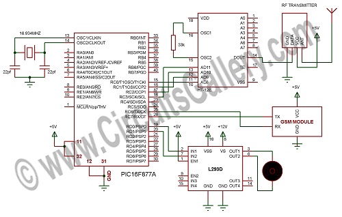
Circuit Diagram
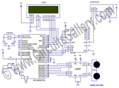
Door receiver circuit
Components Required
- PIC16F877A x2
- RF Module
- GSM Module
- IC L293D x2
- IC HT-12E Encoder
- IC HT-12D Decoder
- Resistor 1K, 33K, 750K
- Capacitor 33pf x4
- Robot kit
- LCD 2×16
- DC gear motor 100 rpm x2
- Crystal 16.934 MHz x2
- Push-button
- 12V 1.2Ah battery
Working of the project
- There are three modules used here in this project, one software module and two hardware modules.
- One of the Hardware modules is connected to a PC which is connected with GSM and RF modules. GSM module is used to send SMS to the owner’s mobile number in case an unknown person is trying to access the robot or open the door.
- RF module is used to communicate with the robot wirelessly; the HT-12E encoder and HT-12D decoder are also used to ensure noiseless wireless communication.
- The other hardware module is connected to a robot with a 12V battery and 2×16 LCD used to display the movement status and authentication status.
- In the software module, MATLAB is used. After recognizing the voice, it will automatically send the letter ‘Y’ which will be received on the first hardware module connected to the PC. PC will send data to the data pin of the HT-12E encoder as ‘1’ via PORTC.
- The robot module receives the RF signal which is then decoded by HT-12D. Then the decoded data is sent to the PORTC of the PIC connected with the robot, thus robot receives ‘1’ and understands that the voice is recognized.
- After recognition by the robot, it will break the first loop and will be ready to receive the signal to move in any direction.
- MATLAB will send letters for each direction when any button is pressed, it also has open and close buttons.
- The door driving system is connected with the first module and L293D motor driver IC, when pressing the button ‘O’ it will open the door and close when ‘C’ is pressed.
- Actually, MATLAB is sending letters when we are pressing buttons but the robot will accept it only after getting a ‘1’.
- The hardware connected with the PC will receive serial data, and then it converts it into parallel data and send it through the HT-12E encoder via an RF transmitter.
- RF receiver will receive the data and convert it into parallel and then feed it to PIC, it will drive the motor depending on the parallel data (0001, 0010, 0011, 0100, 1000, 1001, 0111), these received parallel data are connected to PORTC of PIC.
- Actually, PORTC of PIC has 8 bits but HT-12D has only 4 bits, this is compensated by simply grounding the last four bits (MSB) of PORTC.
Conclusion
Hope this computer-controlled robot project will help you both practically and academically. This project will blow any ones mind and its really cool to control.
Subscribe to our newsletter
& plug into
the world of circuits