How to Test a TRIAC? | Testing Procedure with a Multimeter or Ohmmeter
With some easy steps, you can test a Triac using a digital multimeter or an ohmmeter. While using a multimeter, a digital multimeter is suggested for this test as these kinds of multimeters show more accurate readings than analog ones.
Electrical AC power control using a Triac is extremely efficient, especially when used appropriately to regulate resistance-type loads like tiny universal motors, heaters, and incandescent bulbs, which are commonly found in portable power tools and small appliances.

Testing Procedure of TRIAC
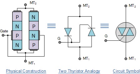
Triac is the most widely utilized member of the thyristor family. It is a five-layer, three-terminal power semiconductor device. On the same chip, it features a pair of phase-controlled SCRs coupled in inverse parallel. Also, it is a bidirectional device, which implies that current can flow in both ways.

How to Test TRIAC with a Multimeter?
Step 1
Select resistance mode on the multimeter. Using a P-N junction diode, determine the polarity of the ohmmeter lead. When a positive lead is linked to the anode and a negative lead is connected to the cathode, continuity is established.
Step 2
When a positive voltage is provided to MT1 and a negative voltage is provided to MT2, the Triac remains in its off state with gate current zero. Similarly, when a positive voltage is provided to MT2 and a negative voltage is applied to MT1 with a gate current of zero, the Triac stays in its off state.
Step 3
The ohmmeter should show no continuity through the Triac in steps 1 and 2 of Triac testing. This suggests Triac has a high level of resistance. On the other hand, if the ohmmeter indicates continuity through the Triac in steps 1 and 2 of Triac testing. It denotes that the Triac has a short circuit and is faulty.
Step 4
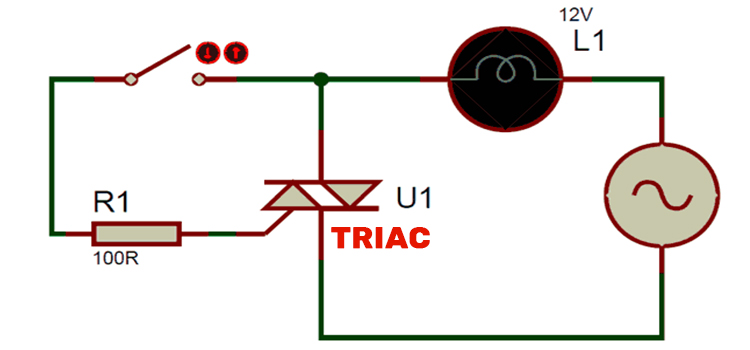
Now, if the Triacs gate receives a positive voltage, the device turns on, regardless of whether MT1 is positive with respect to MT2 or MT2 is positive with respect to MT1. This may be accomplished by connecting the Triacs gate to a positive lead (MT1 or MT2, depending on which terminal has a positive voltage as measured using an ohmmeter).
Step 5
It requires the Triac to switch on and display extremely low resistance or continuity between MT1 and MT2. If Triac displays continuity, the Triac under test is OK. If Triac does not switch on according to step 8, Triac has a very high resistance and is faulty.
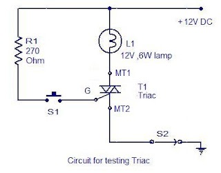
Circuit for Testing a Triac

How to Test a Triac – DIY Electronics Projects, Circuits Diagrams, Hacks, Mods, Gadgets & Gizmos
This is another method for testing a Triac. This circuit may be used to test almost any type of Triac. This circuit is only a simple configuration to explain the basic operation of a Triac. Connect the Triac to the circuit as shown in the picture and turn on S2. The bulb should not be lit.
Now, press the S1 pushbutton switch. The bulb must light up to indicate that the Triac has been turned on. When you let go of the push button, you can watch the lamp go out. If the foregoing tests are positive, the Triac is likely to be healthy.
Where Can You Use a Triac?
In most control applications, it has changed SCR by virtue because of its bidirectional conductivity. Some of its primary applications include phase control circuits, liquid level control, lighting control, temperature management, motor speed regulation, and power switches, among others.
AC Power Control
A Triac control circuit regulates AC power to a load by switching on and off between the negative and positive half cycles of the input sinusoidal signal. D2 is reverse biased, whereas D1 is forward biased, and the gate terminal is positive in relation to A1.
Remember that this is true for the whole positive half cycle of the input voltage. During the negative half-cycle, diode D1 is reverse-biased, whereas diode D2 is forward-biased. As a result, the gate becomes positive in relation to terminal A2, the point at which conduction begins is managed by adjusting the resistance R2.
Frequently Asked Questions
What triggers a TRIAC?
The majority of Triacs may be activated by adding a positive or negative voltage to the gate (an SCR requires a positive voltage). SCRs and Triacs continue to conduct after being triggered, even if the gate current stops, until the main current falls below a particular level known as the holding current.
Conclusion
Circuit testing must be done when the power control device is unplugged from the main power source. You should always be conscious of your safety while doing such activities.
Subscribe to our newsletter
& plug into
the world of circuits