How to Test an Amplifier with an Oscilloscope | A Comprehensive Guide
Oscilloscope testing of amplifiers is a useful method for assessing their performance and identifying problems with audio systems. An oscilloscope gives you the ability to see electrical impulses and measure different parameters, which helps you understand how the amplifier behaves.
This entails several steps, such as assembling the oscilloscope, viewing the waveform, and testing for distortion, frequency response, and stability. We will look at the methods and procedures needed to use an oscilloscope to test an amplifier in this article.
How to Test an Amplifier with an Oscilloscope
An oscilloscope is a versatile tool that can be used to test a variety of electronic devices, including amplifiers. By observing the waveform of the amplifier’s output, you can assess its performance and identify any potential problems. In this article, we will provide a step-by-step guide on how to test an amplifier with an oscilloscope.
Equipment Needed
Before you begin, you will need the following equipment:
- Oscilloscope
- Function generator
- Dummy load
- Connecting cables (BNC to BNC, BNC to alligator clips)
Step-by-Step Guide
- Connect the function generator to the amplifier’s input: Use a BNC to BNC cable to connect the function generator’s output to the amplifier’s input.
- Connect the amplifier to the dummy load: Use a pair of BNC to alligator clips to connect the amplifier’s output to the dummy load. The dummy load is a resistor that mimics the impedance of a speaker, preventing damage to the amplifier.
- Connect the oscilloscope to the amplifier’s output: Use a BNC to BNC cable to connect the oscilloscope’s probe to the amplifier’s output.
Set up the oscilloscope
- Set the oscilloscope’s time base to a suitable setting. A good starting point is 1 millisecond per division.
- Set the oscilloscope’s voltage scale to a suitable setting. You should be able to see the entire waveform without clipping.
- Generate a sine wave: Set the function generator to output a sine wave. Start with a low frequency, such as 1 kHz, and gradually increase the frequency until you reach the desired range for your amplifier.
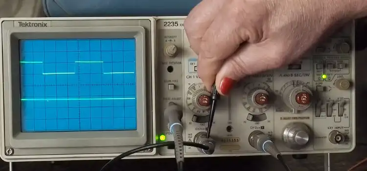
Observe the waveform
- The waveform should be a smooth, symmetrical sine wave. If the waveform is distorted, it indicates that the amplifier is not functioning properly.
- Measure the peak-to-peak voltage of the waveform. This will give you an idea of the amplifier’s output voltage.
- Observe the waveform as you increase the input voltage. The amplifier should be able to produce a clean waveform up to its maximum output voltage.
Distortion test
- Increase the input voltage until the waveform starts to distort. This is known as the clipping point.
- Measure the input voltage at the clipping point. This will give you an idea of the amplifier’s power output.
- The amplifier should be able to produce undistorted output up to its rated power output.
Test for frequency response
- Sweep the frequency of the input sine wave from a low frequency to a high frequency.
- Observe the waveform at different frequencies. The amplifier should produce a clean waveform across its frequency range.
- The amplifier should have a flat frequency response, meaning that it should amplify all frequencies equally.
Stability test
- Observe the waveform for any signs of instability, such as oscillation or ringing.
- The amplifier should be stable at all frequencies and output levels.
Additional Tips
Always use a dummy load when testing an amplifier. This will prevent damage to the amplifier and the oscilloscope. Be careful not to overload the amplifier. Overloading can damage the amplifier and distort the waveform. Use a shielded cable to connect the function generator to the amplifier. This will help to minimize noise. If you are not sure how to use an oscilloscope, consult the user manual or refer to online tutorials.
Frequently Asked Questions
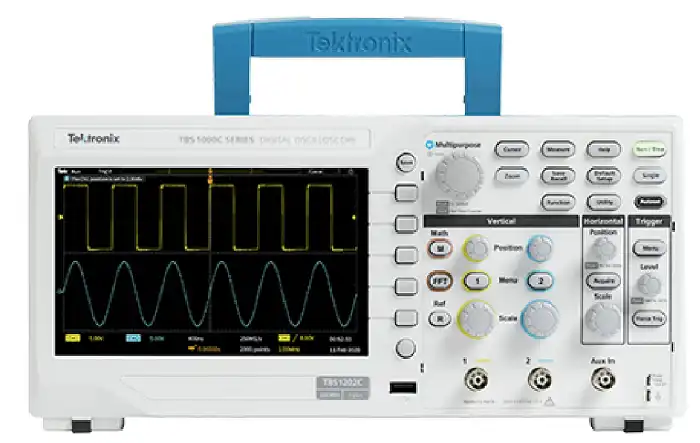
Can I use any type of oscilloscope to test an amplifier?
Yes, you can use different types of oscilloscopes, including analog, digital, or mixed-signal oscilloscopes (MSOs), to test an amplifier. However, ensure that the oscilloscope has the necessary bandwidth and input voltage range to accommodate the amplifier’s signals.
What if I don’t have a function generator to test the frequency response?
If you don’t have a function generator, you can use audio test tones or music tracks with known frequency content as input signals. The important aspect is to vary the frequencies across the audio spectrum to assess the amplifier’s response.
What should I do if I encounter abnormal waveforms or behavior during testing?
If you encounter abnormal waveforms or behavior during testing, it may indicate issues with the amplifier. Double-check the connections, ensure proper grounding, and inspect the amplifier for any visible damage. If the problem persists, consult a qualified technician or seek professional assistance for further troubleshooting and repair.
To Conclude
Testing an amplifier with an oscilloscope is a valuable tool for assessing its performance and identifying any potential problems. By following the steps outlined in this guide, you can learn how to test your amplifier and ensure that it is functioning properly.
Subscribe to our newsletter
& plug into
the world of circuits