How to Use Oscilloscope to Measure Voltage | Measuring AC & DC Voltage with an Oscilloscope
The most basic technique of measuring voltage is to count the number of divisions a waveform spans on the vertical scale of an oscilloscope. The best voltage measurements are obtained by adjusting the signal to cover the majority of the display vertically.
Most oscilloscopes can only monitor voltage directly, not current. The voltage dropped across a shunt resistor is one method for measuring AC current with an oscilloscope.
How to Measure Voltage Using an Oscilloscope
To take measurements using an oscilloscope, first connect the electrical signal you want to observe to one of the oscilloscope’s inputs, which are commonly labeled A and B. To measure AC or DC voltage, perform the following steps regarding the specific voltage.
DC Voltage
To measure the voltage of a direct current (DC) signal with an oscilloscope, perform the following steps:
- Turn on the oscilloscope without attaching the input signal. A DC signal will appear flat on your oscilloscope’s display.
- With the oscilloscope line set to vertical, place it above the zero-volt level.
- Then, connect the DC signal path to one of the oscilloscope’s inputs. When you put in the signal, the oscilloscope line on the vertical axis will alter.
- To find the DC signal voltage, count the number of vertical divisions that your oscilloscope line moves and multiply the number of vertical divisions by the volts/division.
AC Voltage
Perform the following steps to measure AC voltage:
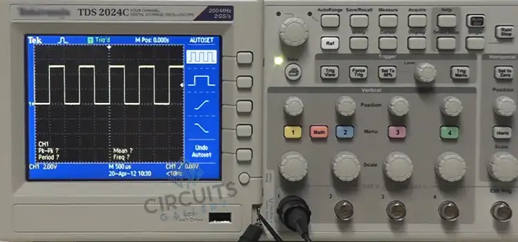
- To measure the alternating current (AC) amplitude using an oscilloscope, first, connect the AC signal to one of the oscilloscope’s inputs before optimizing the signal. The alternating current signal will oscillate and resemble a sine wave.
- The amplitude of the signal will be determined by counting the number of vertical divisions between the signal’s highest and lowest positions (i.e. its peak and trough).
- The amplitude in volts can be calculated by multiplying the number of vertical divisions by the volts/division setting.
Can Oscilloscope Measure AC Voltage
To measure the alternating magnitude, perform the following steps:
- Connect the alternating current signal to one of the inputs of your digital oscilloscope and optimize the signal. Count the number of horizontal divisions in your oscillating signal from one high point to the next (i.e. peak to peak).
- To determine the signal’s period, multiply the number of horizontal divisions by the time/division. The frequency of the signal can be calculated using the following equation: frequency=1/period.
Oscilloscopes are built with a flat, continuous frequency response over the whole bandwidth range. Although some offset or scaling may be necessary, they may easily measure AC signals when in DC coupling mode. That’s what they’re designed for.
Does Oscilloscope Measure Current or Voltage
An oscilloscope’s principal function is to measure voltage waveforms. These waves are exhibited on a graph. These graphs can tell you a lot about a signal, including a signal’s timing and voltage values, and an oscillating signal’s frequency.
Oscilloscopes, at their core, present a voltage vs time plot for one or more signals. This voltage vs. time graph is sometimes referred to as a waveform. This waveform is presented by utilizing a probe to connect a specific signal on the device under test (DUT) to the oscilloscope.
How Do You Measure Battery Voltage on an Oscilloscope
You can measure the battery voltage with an oscilloscope that has a direct-coupled deflection amplifier or terminals. It is for connecting directly to the cathode-ray tube’s deflection plates. But this is only useful in certain situations, such as when you’re using the oscilloscope to take other measurements.
Conclusion
Because of their high input impedance, oscilloscopes will not normally load down the circuit you’re testing. But oscilloscopes are built primarily for waveform observation. And are generally less accurate than other forms of testing equipment commonly used to measure DC voltages.
Subscribe to our newsletter
& plug into
the world of circuits