How to Wire a 5 HP Air Compressor | Step-by-Step Guide
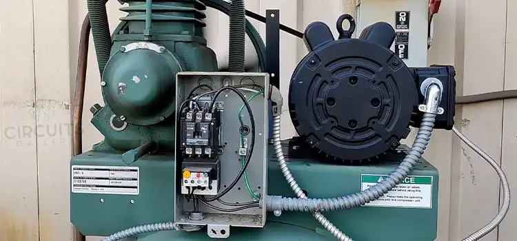
An air compressor is a versatile tool that can power pneumatic equipment, inflate tires, and more. Wiring a 5 HP air compressor can be a daunting task, but it is important to do it correctly to ensure safety and optimal performance.
This guide will provide a step-by-step overview of wiring a 5 HP air compressor, covering key steps like choosing wiring materials, installing safety devices, connecting the motor, and testing the system.
Required Materials for Wiring a 5HP Air Compressor
- 8 AWG THHN wire
- Appropriate disconnect switch (30A for 240V single phase, 20A for 240V three phase)
- Magnetic motor starter size for compressor motor (7.5 HP rating for 5 HP motor)
- Motor overload protection
- Electrical tape
- Wire connectors/terminal lugs matched to wire gauge
- Conduit and fittings (if running wires through enclosure)
Step-By-Step Process of Wiring a 5 HP Air Compressor
Follow the steps carefully and use extreme caution when working with electrical systems. Pay close attention to all warnings and instructions from the air compressor manufacturer.
Step 1: Choose Appropriate Wiring
Choosing the correct wire size and type is essential for safety and performance. The wire must be able to handle the starting and running amperage draw of the 5 HP motor.
- Wire Size: For a 5 HP 240V air compressor, 8 AWG copper wire is recommended. This allows for up to 40 amps, which covers the peak draw of the motor.
- Wire Type: Use only copper wiring rated for wet locations. Either THHN/THWN or Romex can be used. If running through the conduit, THHN/THWN is required. If buried underground, UF-B wire should be used.
- Conduit: If wiring through conduit, choose 1/2″ or 3/4″ electrical metallic tubing (EMT). Run conduit between the disconnect switch, magnetic starter, and motor.
Step 2: Install Disconnect Switch
The disconnect switch allows you to safely cut power to the air compressor for maintenance. It must be:
- 30A non-fused disconnect switch for single-phase and 20A non-fused disconnect switch for three-phase Air Compressor
- Located within sight of the compressor
- Easily accessible
- Properly rated for the voltage and amperage
Install it on a wall or stationary surface near the compressor. A 30 amp non-fusible disconnect switch is recommended.
Step 3: Install Magnetic Starter
The magnetic starter controls power to the motor and protects it from overloads. It should be:
- Mounted next to the disconnect switch
- Matched to the motor voltage and amperage
A 240V magnetic starter designed for motors up to 7.5 HP will work for a 5 HP air compressor.
Step 4: Connect the Wires
Wiring for Single-Phase Air Compressor:
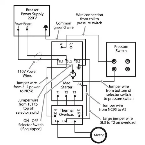
- Connect power leads from the disconnect switch to L1 and L3 terminals on the motor starter.
- Connect motor wires T1 and T3 to motor starter output terminals.
- Connect ground wire to ground lug on starter.
Wiring for Three-Phase Air Compressor:
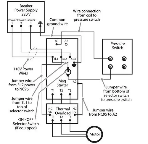
- Connect power leads from the disconnect switch to the L1, L2, and L3 terminals on the motor starter.
- Connect motor wires T1, T2, and T3 to motor starter output terminals.
- Connect the ground wire to the ground lug on the starter.
Step 5: Connect the Motor
Attach the wiring to the motor using insured connectors sized for the wire gauge being used. Connections must be tight and secure. Follow the motor wiring diagram exactly. Verify proper motor rotation direction. Correct if needed by swapping two power leads on the motor starter.
Step 6: Test the System
Before using the air compressor, test it:
- Turn on the disconnect switch.
- Start the magnetic starter. The motor should begin rotating.
- Stop the starter. The motor should continue rotating.
- Restart and stop the motor several times to verify proper operation.
- Turn off the disconnect switch when done.
If any issues occur, re-check all connections before attempting operation.
Safety Tips
- Use extreme caution when working with electrical systems.
- Ensure proper grounding to avoid shocks.
- Keep hands and loose clothing away from moving parts once started.
- Follow all manufacturer safety guidelines.
Troubleshooting
The motor won’t start: Check wire connections, fuses/breakers, overload settings, and starter.
- Starter won’t engage: Verify incoming power supply and condition of starter.
- Tripping breaker/blown fuse: Confirm wires are properly sized. Check for shorts.
- Overheating wires: Inspect for loose connections and undersized wires.
- Noise/vibration: The mounting may be loose. Check bearings and alignment.
Frequently Asked Questions (FAQs)
Q1. What Size Breaker Is Needed for a 5 HP Air Compressor?
Answer: A 30-amp 240V breaker is recommended for a 5 HP air compressor. The breaker must be properly rated for the starting current and running amps of the motor.
Q2. What Size Wire Should Connect the Pressure Switch to the Starter?
Answer: A 16 or 18 AWG wire is appropriate to connect the low-voltage control circuit between the pressure switch and magnetic starter. This control circuit carries minimal current.
Q3. Can I Mount the Starter and Switch Remotely from the Compressor??
Answer: Yes, you can mount them remotely if needed, but ensure they are protected inside an electrical box and located as closely as practical. Extended wire runs are not recommended. Keep wire lengths as short as possible.
To Conclude
Wiring a 5 HP air compressor properly involves selecting adequate wiring, installing safety devices, making secure connections, and testing operations.
Follow each step carefully to ensure optimal performance and safety. Reference the manufacturer’s instructions as needed. With caution and attention to detail, you can wire your powerful air compressor for efficiency and reliability.
Subscribe to our newsletter
& plug into
the world of circuits