How to Zoom In Oscilloscope? | A Detailed Guide for You
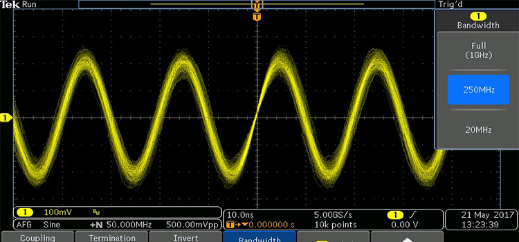
To zoom in or out a signal in an oscilloscope, you need to change the scales of the axes. Use the knob for the horizontal axis and set the µs/div to a lower value. This will allow you to zoom on your signal horizontally. To zoom vertically, set the volts/div of your oscilloscope to a lower value.
Zooming in on waveforms allows you to view a detail of the signal impossible to see on the original waveform. This can be used to remove noise from a repeating signal. Averaging produces a cleaner image with the same frequency resolution as the original shot but a higher vertical resolution.
Methods to Zoom In Oscilloscope?
In the case of signals with a high dynamic range, creating a function zoom the region of the waveform can be useful. There are various methods for zooming in on signals. The methods other than changing the scales of your scope are illustrated below:
Method-1: Adding a MathFunction
Almost all modern scopes incorporate one or more math functions or provide zoom windows that include both vertical and horizontal scaling independent of the main window. Perform the following steps to zoom in on your scope’s signal:
- To zoom with a function, for example, add a function to magnify channel 1 of the scope.
- The main window can now display the complete waveform, and the magnify option can zoom in on the area of interest.
- The arithmetic function (zoom) will not have a higher resolution than the scope produced with the channel waveform, but it will show more information.
Method-2: Setting the Trigger
- Set the trigger to the data point of interest.
- It is not necessary to maximize the memory because scopes will generally automatically maximize memory to a suitable extent.
- Determine the length of the SPI frame and configure the time base to capture the entire frame (say 100us).
- Make a single acquisition.
- Now you can zoom in the datapoint by checking that frame out.
Method-3: Nico’s Method
Nico cited the example of an SPI frame in which you are interested in a certain bit but also want to inspect the entire frame. Nico’s method is as follows:
- Set the trigger to the data point of interest.
- Set the memory to the maximum.
- Set the time base so that the selected data point fills the screen.
- Perform a single collection.
- Examine the data point as it’s now zoomed in.
- Zoom out to examine the rest of the SPI frame.
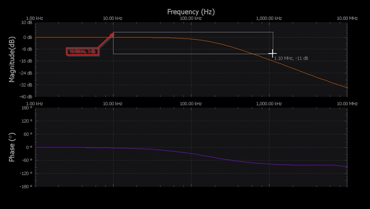
How Do You Zoom In on Scopy?
After collecting the signal, zoom in on the desired location by holding and dragging on the minimum and highest frequency of your scopy. The figure is shown below. This will enlarge both the bode magnitude and phase plots. Use the display options in the settings panel to zoom in or out on magnitude or phase.
How Do You Operate an Oscilloscope?
Because of the unlimited variety of signals available, you’ll never operate an oscilloscope in the same way twice. However, there are some processes that you can count on performing almost every time you test a circuit. Now we’ll look at an example signal and the methods needed to measure it.
- First and foremost, you must choose a probe. For the majority of signals, the simple passive probe provided with your scope will be enough.
- Set the attenuation on your probe before connecting it to your scope. The most common attenuation factor, 10X, is usually the best all-around option. However, if you’re trying to measure a very low-voltage signal, you might need to utilize 1X.
- Turn on channel-1 and turn off channel-2. Channel-1 should be set to DC coupling.
- Set the trigger source to channel 1; no other sources or substitute channels should be used.
- Set the trigger mode to auto and the trigger type to the rising edge (as opposed to single). Check that the scope probe attenuation on your scope corresponds to the setting on your probe.
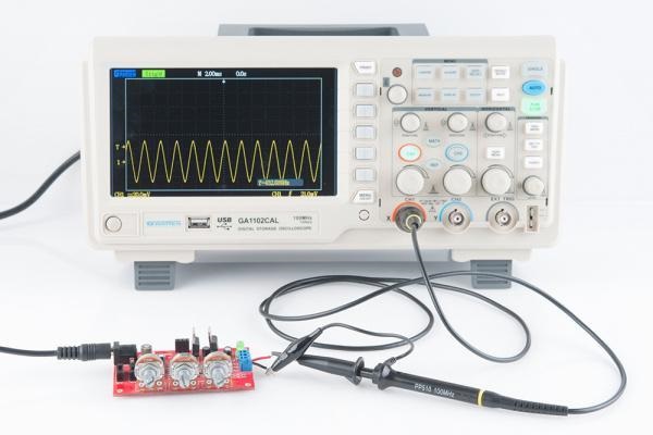
- Connect your circuit to the scope as in the following figure and set the scales of the axes.
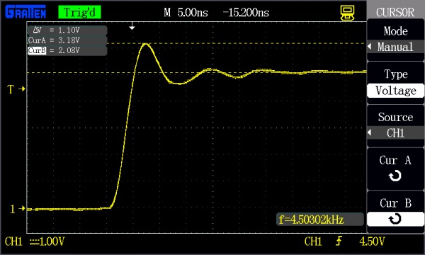
- Now set the cursor as the following figure to measure the frequency and amplitude of the signal.
How Do You Measure Gain on an Oscilloscope
Perform the following steps to measure the gain of your signal:
- Use channel-1 of your scope to monitor the input signal and channel-2 to monitor the output signal.
- Measure the amplitude of the input and the output.
- Now find the difference by dividing the output by the input and you’ll get the gain of the signal.
Frequently Asked Questions
How much voltage can an oscilloscope measure?
The highest voltage is ±300V. It makes no difference what the scope settings are or if the voltage is AC or DC. Any voltage less than that will not harm the scope, but depending on the settings, what you see on the display may or may not be relevant.
Conclusion
Zooming in on waveforms is necessary because it allows the observation of electrical signals, particularly time-varying ones. The signals can move slowly or quickly. The oscilloscope offers amplification and delay capabilities that allow you to see a portion or all of the signal.
Subscribe to our newsletter
& plug into
the world of circuits