Ice Cube Relay Wiring Diagram | Explained In 5 Steps
An ice cube relay is a type of electromagnetic relay found in automotive and industrial applications. Its tiny size and ability to handle strong currents distinguish it. Typically, ice cube relays are used to regulate high-power loads such as electric motors, spotli2ghts, and compressors.
Coil terminals, common terminal, normally open (NO) terminal, and normally closed (NC) terminal are four terminals of an ice cube relay. It’s important to keep in mind that these four terminals need proper wiring for the ice cube relay to function properly. Now let’s get to know more about the wiring of an ice cube relay.
Wiring Diagram and How to Wire an Ice Cube Relay
Perform the following steps to wire an ice cube relay:
Step 1: Connect the positive terminal of the battery to one of the relay’s coil terminals.
Step 2: Connect the negative end of the battery to the relay’s other coil terminal.
Step 3: Connect the battery to the relay’s common terminal.
Step 4: Connect the battery’s positive connection to the relay’s NO terminal.
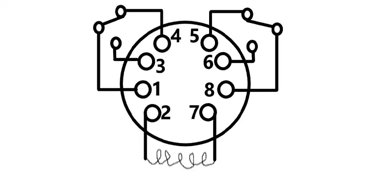
Step-5: Ensure that the connection is given according to the following figure:
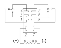
Figure 1: Ice Cube Relay Wiring Diagram
What to Notice While Wiring Ice Cube Relay?
The factors that you must notice while wiring an ice cube relay are given below:
- Excessive use of specification ranges such as coil rating, contact rating, and switching life should be avoided at all costs. This could result in abnormal temperature, smoke, and fire.
- When the relay is powered up, never touch any live parts. This could result in an electrical shock. Make sure that the power is turned off when installing, maintaining, or troubleshooting a relay (including connected items such as terminals and sockets).
- When connecting terminals, please refer to the internal connection diagrams in the catalog to guarantee proper connections. Be aware that a faulty connection can result in an unexpected operating error, abnormal heating, and fire.
- If there is a chance that incorrect adhesion or contact would jeopardize assets or human life, take extra care.
Why Is a Wiring Diagram Necessary for an Ice Cube Relay?
Connecting an ice cube relay without a wiring diagram can be tricky, if not dangerous. If the relay is not properly connected, it may cause damage to itself or other components in the circuit. In the worst-case scenario, it may potentially start a fire.
What Are the Common Connections on an Ice Cube Relay?
The following are the common connections on an ice cube relay:
- Coil connections: The relay coil is powered by these two connections. When the coil is turned on, it produces a magnetic field that attracts the relay contacts together.
- Common affinities: An ice cube relay has two common connections. The ordinarily open (NO) and usually closed (NC) contacts share these connections.
- Contacts that are normally open (NO): These contacts are open when the relay is not powered. The NO contacts close when the relay is activated.
- Contacts that are normally closed (NC): These contacts are closed when the relay is not powered. The NC contacts open when the relay is activated.
Conclusion
Ice cube relay has normally open (NO) switch contacts, which means that when the relay coil is de-energized, the switch will be in the open (off) position. A switch’s “normal” status is its unstimulated resting state.
Subscribe to our newsletter
& plug into
the world of circuits