Is a Resistor an Active Load? | A Detail Explanation
In electronics, a component or circuit that can change its impedance or behavior based on external factors or feedback is known as an active load. A resistor is a passive electronic component with a fixed resistance value. Therefore, it is not considered an active load.
In this article, we will discuss in detail.
What is an Active Load?
An active load is a component that actively varies its electrical impedance based on external feedback. Active loads are typically used to stabilize and control the operation of other active electronic devices, such as transistors and amplifiers.
Active loads can change their electrical impedance or resistance dynamically. This can maintain specific operating conditions for other active devices in the circuit. In amplifier circuits, they can be used to control gain and distortion. They can also be used in voltage regulation circuits as well.
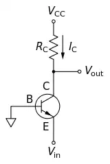
Figure 1: Basic NPN common base circuit with active load
In the NPN circuit of the figure, the current flowing through the resistor of active load from Ohm’s law,

Why is Resistor Not an Active Load?
As a resistor is a passive electronic component with a fixed resistance value, it’s considered a passive element. Here’s why a resistor is classified as a passive component:
- Fixed Resistance Value: Active loads can adjust their impedance based on external factors. A resistor’s primary function is to provide a specific resistance value to a circuit. The resistance value is constant and does not change unless the physical resistor is replaced with a different value.
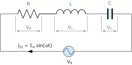
Figure 2: Series RLC circuit
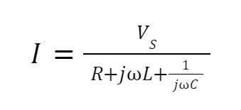
In the series RLC circuit, current flowing through the resistor,
- No Amplification or Control: Active loads play an important role in amplifying signals or regulating the operation. A resistor does not amplify or control the signal passing through it. It simply dissipates electrical energy in the form of heat as current flows through it.
- No Feedback or Adjustability: Active loads can change their characteristics to stabilize or control a circuit as needed. Resistors, in contrast, do not have the ability to provide feedback or adjust their resistance value based on circuit conditions.
Frequently Asked Questions and Answers
What is an example of an Active Load?
Examples of active loads include transistors and semiconductor devices like amplifiers. They amplify, rectify and alter the waveform of current or voltage. They are the main pillars of electronic systems.
Is a Resistor a Load?
In a more general sense, a circuit that converts electrical energy into light, heat, or useful motion is called a load on the circuit. As a resistor dissipates electrical energy in the form of heat as current flows through it, it’s considered a load.
Are Diodes Active or Passive?
Components incapable of controlling current by means of another electrical signal are called passive devices. Resistors, capacitors, inductors, transformers, and even diodes are all considered passive devices.
Conclusion
Active adjust their impedance or behavior to control and stabilize other electronic components, like transistors and amplifiers. However, resistors are passive components that provide a fixed and do not actively participate in circuit control or signal amplification. Therefore, resistors are not active loads.
Subscribe to our newsletter
& plug into
the world of circuits