Jenn Air Cooktop Wiring Diagram | Guidelines
The Jenn Air cooktop proves that advanced kitchens have become innovative culinary center points. Due to their innovative and elegant designs, these modern appliances are a popular choice for individuals hoping to advance their culinary involvement.
Jenn-Air is a well-known producer of high-end kitchen appliances, notably cooktops. A high-end kitchen appliance with a cooking surface is a Jenn-Air cooktop. These cooktops are recognized for their cutting-edge design, inventive functionality, and creative cooking strategies.
We’ll look into the realm of Jenn Air Cooktop wiring schematics in this article and explain how they work.
Basic Components of a Jenn Air Cooktop
Before delving into the wiring diagram, let’s briefly review the fundamental components of a Jenn Air cooktop:
1. Cooktop Surface: This is where the cooking happens, featuring burners or induction elements.
2. Control Panel: You may select cooking settings, adjust the heat setting, and manage various operations utilizing the user interface.
3. Wiring System: The cooktop is powered and controlled through a network of wires and other parts.
4. Power Supply: The source of electrical energy that provides power to the cooktop.
5. Security Features: Circuit breakers, thermal switches, and wires, all of which are security components, are built-in safety measures against electrical issues and overheating.
Wiring Diagram of Jenn Air Cooktop
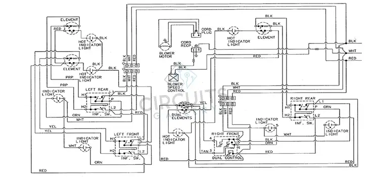
Image 1- Wiring Diagram of Jenn Air Cooktop
Understanding the Wiring Diagram
Let’s look at the main components of a wiring diagram for a Jenn Air cooktop now:
1. Components
The cooktop’s various parts, including the burners, switches, indication lights, and security devices, will be represented by symbols and labels on the diagram. According to how they perform, each component is related to the others.
2. Wiring Paths
The diagram will show the paths that wires travel to connect different components, showing how electrical power flows through the cooktop. Both high-voltage and low-voltage connections fall under this category.
3. Color Coding
Wiring diagrams commonly utilize color coding to distinguish between wires and denote their purposes. For hot cables, neutral wires are commonly white, while ground wires are typically green or uncovered. You must comprehend these color codes to introduce the item accurately and safely.
4. Circuitry
On a Jenn Air cooktop, each burner or cooking zone has its own circuit. The wiring schematic will show the circuits for each burner, outlining how power is delivered and independently controlled.
5. Safety Features
The diagram will also incorporate security features, such as thermal switches or fuses, and their connections. To prevent overheating or electrical accidents, these qualities are vital.
Troubleshooting with the Wiring Diagram
Knowing the wiring diagram for your Jenn Air stove in detail can be quite helpful when diagnosing electrical issues. Here are some typical circumstances where the graphic can be valuable:
1. Burner Not Heating
To find out which electrical wires from the control panel are going to the burner element, use the schematic in case a burner isn’t heating up. This can be used to find damaged wiring, switches, or burners.
2. Indicator Lights Not Working
If the indication lights on the control panel aren’t working, you can utilize the diagram to figure out which connections and components are in charge of these indicators.
3. Safety Device Tripped
If a safety device, such as a thermal switch or fuse, trips, a wiring diagram can help you locate the device and understand the conditions that trigger the safety mechanism.
4. Power Supply Issues
If your cooktop doesn’t have power, you can use a diagram to trace the path of the power source, thereby identifying potential faults in the wiring or power source.
Frequently Asked Questions and Answers
Is it safe to attempt repairs using the wiring diagram without professional help?
It is always advisable to look for professional help when performing electrical installations or repairs, even though the wiring diagram clearly illustrates how the cooktop’s electrical framework is set up. Damage to a stove or electrical risks could come from improper handling.
What should I do if I can’t understand the symbols and notations on the wiring diagram?
Wiring diagrams use common symbols to show all the parts and associations of an electrical system. In case you’re not familiar with electrical symbols, it’s best to consult with an electrician or look at websites that clarify them in great detail.
How often do wiring issues occur with Jenn Air Cooktops?
Wiring issues with Jenn Air cooktops are extremely rare, particularly if they have been installed and maintained accurately. However, sometimes issues might develop from wear and tear over time, just like with any electrical item.
Conclusion
Modern kitchens benefit from the stylish and useful Jenn Air cooktop and other appliances. Its wiring diagram must be understood to perform maintenance and troubleshooting. The wiring schematic determines whether you are a skilled do-it-yourselfer or just a smart homeowner when it comes to maintaining your stove’s performance.
Subscribe to our newsletter
& plug into
the world of circuits