Meter Socket Wiring Diagram | Just 3 Steps
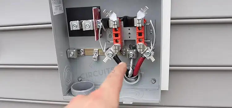
Consider your home’s electrical system to be a massive power distribution network. A meter socket is the entry point for electricity. It connects the utility company’s power source to your home’s electrical system. Your meter socket must have proper wiring.
Service entrance wires, load conductors, and the grounding conductor are the wires of a meter socket that need specific care while wiring it. The wiring schematic for a meter socket may differ depending on the type of electrical service and the meter socket in use. Now let’s dig more into the topic.
How to Wire a Meter Socket
A meter socket wiring diagram is a diagram that demonstrates how to connect the electrical service entrance wires from the utility provider to the building’s electrical panel. Following is the figure and the steps that you need to follow while wiring a meter socket:
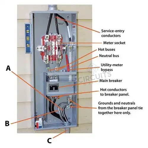
Figure 1: Meter Socket Wiring
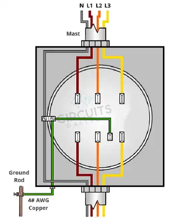
Figure 2: Meter Socket Wiring Diagram
Step 1: Typically, the service entrance wires are black, red, and white. The black wire is the hotline, the red wire is the second hotline, and the white wire is the neutral conductor. The following is how the service entrance wires are connected to the meter socket:
- Connect a black wire to the “L1” terminal.
- Connect the red wire to the “L2” connector.
- Connect a white wire to the “N” terminal.
- Connect the green wire to terminal “G”.
Step 2: The electrical panel’s load conductors are linked to the meter socket as follows:
- Connect a black wire to the “Load L1” terminal.
- Connect the red wire to the “Load L2” connector.
- Connect a white wire to the “Load N” terminal.
Step 3: The grounding conductor from the electrical panel is linked to the meter socket’s “G” terminal.
Safety Measurements That You Need to Take While Wiring a Meter Socket?
The factors that you must notice while wiring a meter socket are given below:
- Before working on any electrical wiring, always switch off the power at the main breaker.
- Check that all electrical connections are snug and secure.
- Use wire and connectors that are the correct size for the amperage of the electrical service.
- If you are unsure about wiring the meter socket yourself, use a trained electrician.
Disconnecting Power When Installing a Meter Socket
To disconnect power when installing a meter socket, do the following:
- Disconnect the electricity at the main breaker. This will turn off the power to the entire building.
- Remove the old meter socket’s seal. The seal is usually found on the meter socket’s door.
- Disconnect the cables from the service entrance to the old meter socket. Avoid touching any of the wires while they are still active.
- Take the load conductors out of the old meter socket.
- Unplug the old meter socket’s grounding conductor.
- Take the old meter socket out of the wall.
Frequently Asked Questions and Answers (FAQs)
Do I Need a Permit to Install a Meter Socket?
The installation of a meter socket requires a permit, which is determined by your local construction codes. In most circumstances, any electrical work involving alterations to the service entry wiring will necessitate a permit.
What Size and Type of Meter Socket Do I Need?
The size and kind of meter socket you require are determined by the amperage of your electrical service as well as the type of service entrance wire you have:
- Meter sockets in homes are commonly rated for 100, 200, or 320 amps. Because most single-family homes have a 200-amp electrical supply, a 200-amp meter socket is acceptable. If you have a large home or many electrical appliances, you may want a higher-amp meter socket.
- Meter sockets for commercial and industrial use are often rated for larger amperages, such as 400, 600, or 800 amps. These meter sockets are often found in commercial and industrial buildings with heavy electrical loads.
Conclusion
To safely and securely connect to an electrical service, each type of watt-hour meter requires a meter socket. Outside your house, you will most likely discover a single-meter socket. Single-meter sockets are commonly found in single-family houses and in some business applications.
Subscribe to our newsletter
& plug into
the world of circuits