Micro Inverter Wiring Diagram | A Simple Microinverter Wiring Guide
Micro inverters play a critical role in expanding the output of solar panels by converting the direct current (DC) produced by individual solar panels into alternating current (AC), which may be utilized to power homes and businesses.
In this article, we’ll look at the sophisticated wiring diagrams utilized in microinverters and how they assist us in utilizing solar energy.
The Basics of Micro Inverters
Before moving on to the wiring diagrams, let’s first clearly understand what a micro-inverter is. Traditional solar power systems utilize a single central inverter to convert the DC electricity produced by several solar panels into AC electricity. Micro inverters, however, are outlined to be mounted on each solar panel, meaning each board contains a particular microinverter.
Components of a Micro Inverter
A micro inverter is made up of a few crucial components, including:
1. DC Input
This solar panel, which produces DC electricity, is connected to the microinverter.
2. Inverter Circuit
The inverter circuit, sometimes known as the brain of the micro inverter, converts DC into AC power.
3. AC Output
The micro inverter’s output receives the AC power it generates, which is then connected to the building’s electrical system.
4. Monitoring and Communication Devices
Homeowners can remotely check on the performance of particular panels thanks to the monitoring and communication functions that are usually included in modern micro inverters.
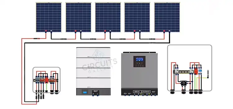
Wiring Diagram of Micro Inverter
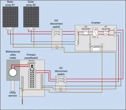
Image 1- Circuit Diagram of Micro Inverter
Micro Inverter Wiring Diagram: How It Works?
Now let’s look at the micro inverter wiring schematic and how it maximizes the generation of solar energy.
1. Micro Inverters for Solar Panels
Each solar panel incorporates a tiny inverter connected to it. The tiny inverter’s DC input is directly connected to the DC output of the solar panel.
Typically, a straightforward but essential connection since it enables the autonomous operation of each panel, minimizing the impact of shading or panel-specific difficulties on the system’s performance.
2. Micro Inverters to AC Combiner Box
The AC output from every micro inverter is then combined utilizing an AC combiner box. This box, which is typically found adjacent to the solar boards, houses the connections from all of the system’s mini inverters. This level enables centralized AC wiring, which makes connecting to the building’s electrical system simpler.
3. Connection to the Main Electrical Panel
The combined AC electricity from the AC combiner box is delivered to the building’s main electrical panel. To balance out the utilization of grid electricity, this panel is in charge of distributing electricity throughout the building.
4. Grid Connection and Net Metering
Through a process known as net metering, excess solar electricity produced throughout the day is frequently sent back into the grid and distributed to homes as credits. The wiring diagram displays a connection point to the grid, guaranteeing a steady flow of electricity between the solar system and the grid.
People Also Asked
What is the voltage of a Micro inverter?
There are two 120-volt leads on the micro inverter. The solar circuit is connected to a double-pole circuit breaker when it is wired into the panel box of your house; two hot wires, each carrying 120 volts from the corresponding branch circuit, are connected to the breaker.
Why micro inverters are used?
Micro inverters take all the available power from each solar panel, transform it into AC on-site, and then deliver it to your fuse box and the power grid. This makes your solar panel system more efficient, so even if a few of your panels have shading concerns, your total output won’t suffer.
How many micro-inverters can be connected?
Two panels are connected by the microinverters, which may produce up to 600W at 240V. They have polarized connectors that are industry standard on the DC side and a daisy-chained connector system on the AC side, making them plug-and-play. One 20A circuit may support a maximum of 7 inverters connected.
Conclusion
The brief overview emphasizes the significance of carefully following the schematic to maintain maximum energy output and ongoing system reliability and acts as a clear direction for improving renewable energy infrastructure. For solar systems to operate steadily and securely, a full understanding of the micro inverter wiring diagram is required.
Subscribe to our newsletter
& plug into
the world of circuits