Mobility Scooter Wiring Diagram | Navigate Your Mobility Scooter’s Wiring
Mobility scooters have developed into indispensable tools for those with mobility issues, giving them more mobility and independence. Understanding the wiring schematics of these scooters is essential for maintenance and troubleshooting since they depend on complex electrical systems to operate well.
We will go into the realm of mobility scooter wiring diagrams in this article, looking at the parts, connections, and electrical theories that power these life-improving machines.
What are the Key Components of Mobility Scooter Wiring?
Mobility scooters have a range of parts, including motors, controllers, throttle assemblies, brakes, and lighting systems. They are powered by rechargeable batteries.
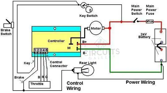
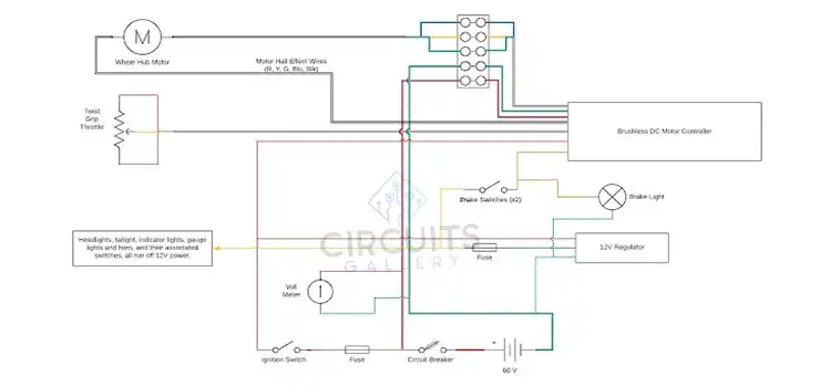
Figure 01: Wiring of A Mobility Scooter
The way these parts are wired together and powered is shown visually in the wiring diagram. Let’s examine the key elements frequently present in a wiring schematic for a mobility scooter:
- Battery Pack: This is the main electrical component of the mobility scooter, and it normally consists of one or more batteries connected in series to produce the required voltage.
- Motor(s): The wheels of a mobility scooter may be driven by one or more electric motors. To regulate the motors’ direction and speed, wiring is essential.
- Controller: The controller serves as the scooter’s brain, controlling how much power is sent from the battery to the motor or motors. It determines how the scooter goes and stops by interpreting input signals from the throttle and brake.
- Throttle Assembly: The potentiometer or hall-effect sensor in the throttle assembly converts the user’s input into a signal that the controller may use to regulate the scooter’s speed.
- Brakes: The mechanical or electromagnetic brakes that are standard on mobility scooters are extremely important for control and safety.
- Lighting and Accessories: The wiring diagram includes any lighting systems, horns, or other accessories that may be included on some scooters.
Understanding the Wiring Diagram of Mobility Scooter
At first sight, a typical wiring diagram for a mobility scooter could seem complicated, however, comprehension can be facilitated by segmenting the diagram. An overview of what you could see in a wiring diagram is provided below:
- Power Source: The battery pack and its connections will be depicted on the schematic. The voltage and capacity of the battery must be taken into account.
- Motor Wiring: The connections between the controller and the motor(s) are shown in this section. It has cables for the ground, the motor power, and occasionally extra wires for sensors and feedback.
- Controller: The controller is a key element with many connections. The throttle, brakes, and other accessories are managed via these connections. It’s crucial to comprehend how signals enter and exit the controller.
- Throttle and Brake Assembly: The wiring for the throttle and brake assemblies demonstrates how the user’s input for speed control and braking is sent to the controller.
- Accessories: The wiring for any lighting or any accessories that the scooter may have is also provided.
Frequently Asked Questions and Answers
How are batteries in scooters wired?
Electric scooter, bike, and go-kart batteries are most frequently wired in series to generate a battery pack with a voltage equal to the total of all the batteries in the pack. Putting batteries in series with one another is referred to as series wiring.
Is the scooter battery AC or DC?
The scooter and the charging device are connected at either end of a wall socket. The charger changes the direct current (DC) power stored in the battery from the alternating current (AC) power coming from the outlet. Your scooter will operate continuously all day thanks to DC power’s constant voltage.
What voltage does a fully charged scooter battery have?
This is true for the majority of lithium-ion battery packs and chemistries that have nominal voltages of 3.6 V, full charge voltages of 4.2 V, and full discharge voltages of 3.0 V. Learn more about the batteries for electric scooters.
To Conclude
Mobility scooter wiring diagrams may at first seem complex, but with a basic knowledge of the parts involved and a methodical approach, they can be useful tools for maintenance and troubleshooting. Individuals may ensure the safe and effective functioning of their mobility scooters by understanding the foundations of these diagrams, eventually improving their mobility and freedom.
Subscribe to our newsletter
& plug into
the world of circuits