NordicTrack Treadmill Wiring Diagram | A Detailed Guide
The NordicTrack brand has become synonymous with high-quality fitness equipment, and its treadmills are no exception. With their advanced features and cutting-edge technology, NordicTrack treadmills are a popular choice among fitness enthusiasts worldwide.
But have you ever wondered what makes these treadmills tick? In this article, we will delve into the world of NordicTrack treadmill wiring diagrams, exploring the intricate electrical components that power these impressive machines.
Wiring Diagram and Connections of NordicTrack Treadmill
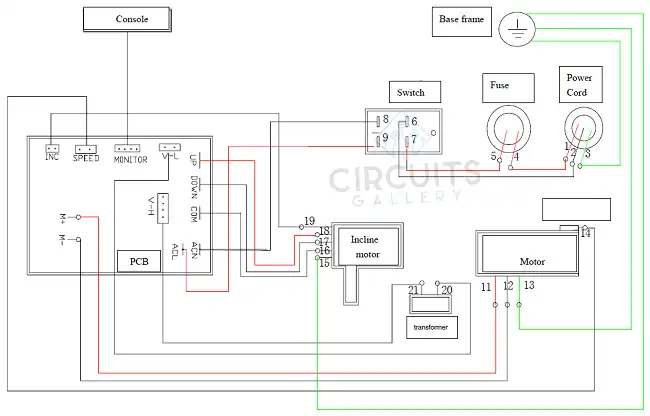
1. Power cord yellow/Green 3 connects with the ground
2. Power cord blue 2 connects with switch 6 (Input voltage 110V-120V)
3. Power corder brown 1 connect with fuse red 4 (Input voltage 110V-120V)
4. Fuse red connect with switch (Input voltage 110V-120V)
5. Connect switch 8 and controller CAN with a red wire (Input voltage 110V-120V)
6. Connect switch 9 and controller ACL with a black wire (Input 110V-120V)
7. Connect incline motor VR with controller INC Voltage(5V)
8. Incline motor red 18 connects with controller UP Voltage(110V-120V)
9. Incline motor black 17 connects with controller DOWN Voltage(110V-120V)
10. Incline motor White 16 connects with controller COM Voltage(110V-120V)
11. Transformer (small end) 20 connect with controller V-L Voltage(8V), big end 21 connect with controller V-H Voltage(110-120V 18V)
12. Motor red 11 connects with controller M+ (below 100V)
13. Motor black 12 connects with controller M- (below 100V)
14. Speed sensor 14 connects with controller speed (below 100V)
15. The console wire connects with the controller monitor voltage (8V-9V)
16. Wiring 3,13,15 connects with the ground
Anatomy of a NordicTrack Treadmill Wiring Diagram
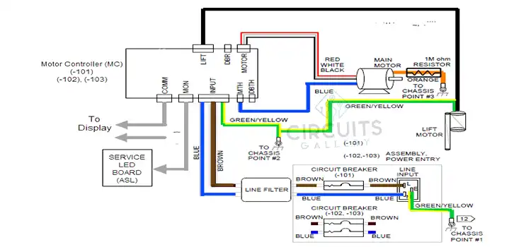
A NordicTrack treadmill wiring diagram consists of intricate symbols and connections representing the treadmill’s electrical system. This section elucidates the fundamental components, such as the motor, control board, sensors, and power supply, found in these diagrams.
- Motor: The motor is the heart of the treadmill, responsible for powering the belt and controlling the speed. The wiring diagram highlights the connections between the motor and other vital components, such as the control board and the power supply.
- Control Panel: The control panel allows users to adjust various settings, such as speed, incline, and program selection. The wiring diagram showcases the intricate connections between the control panel, control board, and other relevant components.
- Power Supply: The power supply is responsible for providing the treadmill with the necessary electrical energy. The wiring diagram reveals the connections between the power supply, control board, and other components, ensuring a safe and efficient power distribution throughout the treadmill.
- Sensors: NordicTrack treadmills are equipped with various sensors, including speed sensors, heart rate monitors, and incline sensors. The wiring diagram illustrates the connections between these sensors and the control board, allowing technicians to diagnose and troubleshoot any issues that may arise.
Troubleshooting Common Issues of NordicTrack Treadmill
If you are having trouble with your NordicTrack treadmill, the wiring diagram can help troubleshoot the problem. To troubleshoot an electrical problem, you will need to identify the electrical component that is causing the problem.
Once you have identified the problem component, you can consult the wiring diagram to see how it is connected to the other electrical components. This can help you to trace the problem and find a solution.
Safety Precautions and Maintenance Tips
When working with any electrical equipment, it is important to take safety precautions. Always unplug the treadmill before working on it. Also, be careful not to touch any live wires. If you are not comfortable working with electrical equipment, it is best to consult a qualified technician.
Modifications and Upgrades
The wiring diagram also plays a crucial role in making modifications or upgrades to the NordicTrack treadmill. Whether it’s adding new features, integrating smart technology, or enhancing performance, the diagram provides a blueprint for understanding how different components interact. This allows enthusiasts to make informed decisions and execute modifications safely and effectively.
Frequently Asked Questions
How can I interpret the symbols and codes in the wiring diagram?
NordicTrack treadmill wiring diagrams use specific symbols and color codes to represent components. Refer to the treadmill’s manual for a legend explaining these symbols. Understanding these symbols is essential for accurate interpretation and troubleshooting.
Can understanding the wiring diagram help me perform regular maintenance on my treadmill?
Absolutely. By understanding the diagram, users can perform basic maintenance tasks such as checking connections, ensuring proper grounding, and inspecting insulation. Regular maintenance, guided by the wiring diagram, can prevent potential issues and extend the treadmill’s life.
Where can I find the wiring diagram for my specific NordicTrack treadmill model?
The wiring diagram is often included in the treadmill’s user manual provided by NordicTrack. If you’ve misplaced the manual, you can usually find it on NordicTrack’s official website by entering your treadmill’s model number in the support or download section.
To Conclude
The NordicTrack treadmill wiring diagram is crucial for technicians and enthusiasts, providing a detailed understanding of the electrical circuitry within the machine. It helps in troubleshooting, repairs, and modifications, ensuring the machine’s performance and ensuring the intricate web of electrical connections makes fitness possible.
Subscribe to our newsletter
& plug into
the world of circuits