Op-Amp Vs Transistor | Which One do Better Amplifying?
Op-amp and transistor are used according to your need. Though op-amp is better for amplifying gain, they are expensive. As the op-amp amplifier is made of different types of transistors. So, in many cases, you can use a transistor instead of the op-amp. The transistor is cheap compared to the op-amp.
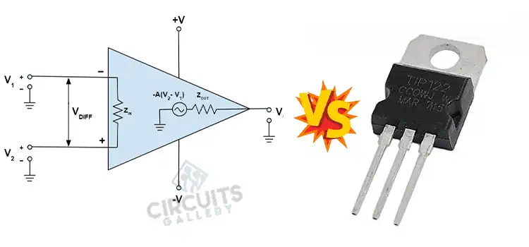
What is the difference between an op-amp and transistor?
The differences between an op-amp and transistor are:
1. Amplifying Gain
Amplifying gain of the op-amp in more than the transistor. The gain of the op-amp and transistor is 1000 and 70 – 100. So, the amplified output will have less stage than the transistor.
2. Stabilisinng Component
Op amp has a built in stabilizing component that the transistor does not have.
3. Build Up
A transistor is built with a p-n-p or n-p-n junction semiconductor. It has three regions emitter, base, and collector.
On the other hand, an op-amp is built with various transistors and other components that are integrated in a circuit. it has five regions, two inputs (inverting and non-inverting), positive and negative power supply, and output.
4. Space and Power
The op-amp requires more space and power compared to the transistor.
5. Cost
The op-amp is more expensive than the transistor.
Are op-amps made of transistors?
Yes, op-amps are made of transistors. The other component of an op-amp is a resistor, capacitor, and diode. The input terminal of an op-amp is connected to the base of the transistors. The emitter terminals are connected to the negative power supply.
The positive power supply is also connected to the two collector terminals. The output signal is obtained from the terminal of the transistors. The collecter voltages can be in the same direction or opposite direction.
Why are transistors used in op-amp?
The op-amp is built up with mainly transistors and resistance. The transistor is used to amplify the signal. A basic operational amplifier or op-amp has two inputs, two power supplies, and one output terminal. The two input is connected to two base terminal of the transistor.
The emitter terminal of the transistor is connected to the negative power supply. And the two collector terminal is connected to the positive power supply. The output is taken from the two collector terminal of the transistor. The output is the difference between the two input signals.
What is the Difference Between Op-Amp and Amplifier?
The difference between an op-amp and an amplifier are:
1. Built Up
An amplifier is a device that amplifies the input signal. It has three terminals. And the op-amp is a high gain electronic voltage amplifier. It has five terminals. Two inputs, two power supplies, and one output. The output voltage is the difference between the input voltages.
2. Amplifying Capacity
The amplifying capacity of an op-amp is more than an amplifier. An op-amp can amplify dc signals but an amplifier has limited capacity.
3. Types
An op amp is an electronic amplifier but an amplifier can be mechanical or electronic.
4. Space and Power
An op-amp consumes more space and power than an amplifier.
Conclusion
In this article, we have discussed the op-amp and transistor. The op-amp is a better choice compared to the transistor or amplifier. The main component of the op-amp is the transistor and resistor. The op-amp is an electronic amplifier. It has a high amplifying gain and amplifies dc signals.
Subscribe to our newsletter
& plug into
the world of circuits