Oscilloscope DC Offset | How to Do Calculation of DC Bias?
DC offset is the mean amplitude displacement from zero. It shifts the reference level of your oscilloscope from the original ground or center zero point. The reference level shifts due to the addition of a DC voltage to your output AC signal. This DC voltage is DC offset.
DC offset can result in asymmetrical clipping. But it’s deliberately added while measuring small signals to bring back the signal’s vertical resolutions.
What is Oscilloscope DC Offset?
DC offset is a necessary feature of the oscilloscope. The reference level could be brought back to the original ground by changing the channel’s reference level.
Following are two signals with DC offset added and without the offset voltage:
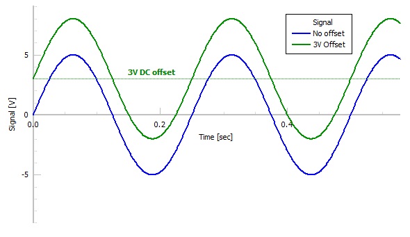
Figure 1: Signals with and without DC offset.
Here the blue signal doesn’t include any DC offset voltage. So, it’s symmetrical about the 0V line. But the green one has a DC offset voltage of +3V. Hence, its reference level got shifted upwards.
What is DC Offset or Bias?
The application of an external DC voltage or biasing is needed to control a circuit. For example, a transistor can properly amplify a signal only when it’s working in the active region. To ensure this, an external DC voltage is deliberately applied between two points to keep the transistor in its active region.
However, if your AC signal has any unwanted DC voltage added to it, it can distort your signal. This type of biasing or DC offset is caused by low-quality equipment.
What is the Function of DC Offset?
DC offsets are unwanted DC signals added to an AC signal. DC offset is the reason for audible clicks. As it shifts your AC signal from its original ground, your signal could get clipped asymmetrically. But when your signal is out of your oscilloscope’s ADC range, the offset brings the signal back in range.
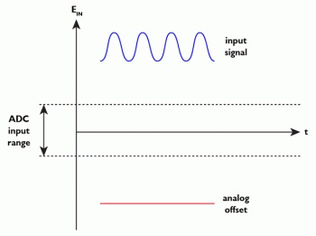
Figure 2: Out-of-range signal.
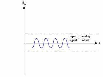
Figure 3: Signal brought into range by DC offset.
How to Calculate DC Offset of an Oscilloscope?
To calculate the DC offset of an oscilloscope you’ve to perform the following steps:
Step-1: Give power to your oscilloscope and turn it on. Now center the oscilloscope reference level to the 0V mark by varying the vertical offset control.
Step-2: Plug in the signal that you want to display on your oscilloscope screen.
Step-3: Adjust the scales of the vertical and horizontal axis of your oscilloscope. Keep modifying the settings until a clear oscillatory signal is displayed.
Step-4: Now count the number of vertical divisions between the 0V line on the oscilloscope and the center of your oscillatory signal.
Step-5: You’ll get the DC offset by multiplying the number of vertical divisions by the volts/divisions.
How Do You Adjust DC Offset on an Oscilloscope?
To adjust the DC offset of an oscilloscope you’ll have to change the reference level of your scope. You can use the position knob to trace the vertical position on the scope’s display. Or you can set the offset to your desired value by entering the voltage you want to be your offset voltage. To do this perform the steps below:
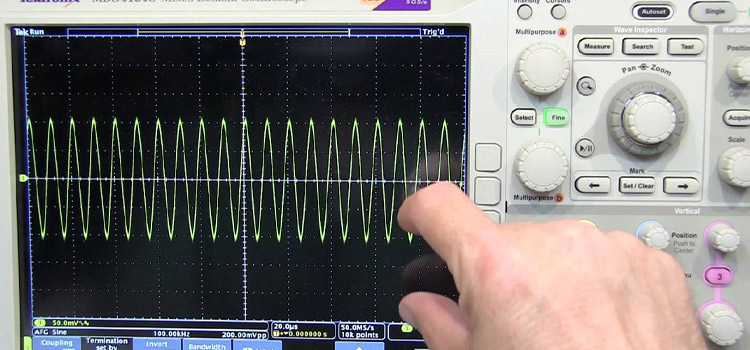
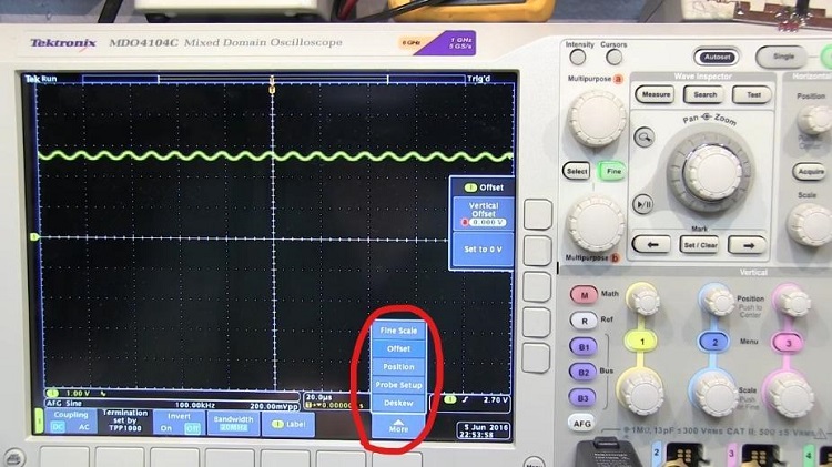
Step-1: Open the vertical menu on your oscilloscope’s display as shown in the figure.
Step-2: Now enter the value you want to be your offset voltage for your signal by the knob marked red in the following figure.
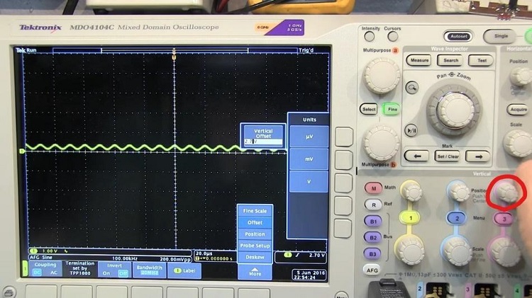
Thus, you can add a DC offset voltage to your signal to nullify the effect of the unwanted offset voltages. This can also help you to view your signal in your desired range.
Frequently Asked Questions
How can you filter the DC offset voltage?
DC offsets are signals with a frequency of 0Hz. So, you can use a capacitor or a high pass filter in your circuit to filter out the DC offset. But that can distort the low-frequency signals of your output.
Conclusion
If the mean amplitude of a periodic function is zero, there is no DC bias or DC offset. Such waves are DC-balanced waves. Some signals are needed to be biased while some aren’t. The DC offset of your oscilloscope helps you to adjust the reference level of your signal to your requirement.
Subscribe to our newsletter
& plug into
the world of circuits