Pool Pump Capacitor Wiring Diagram – A Detailed Guide for You
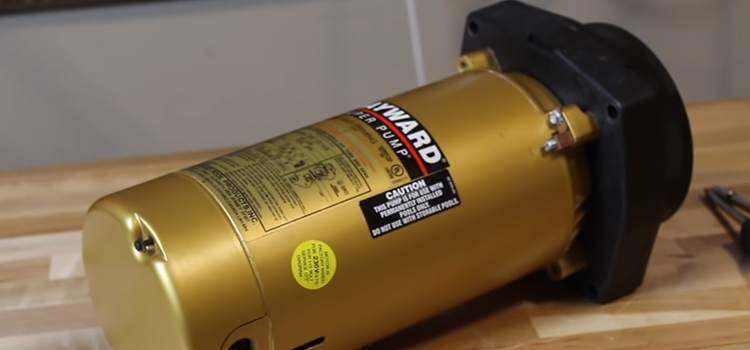
A pool pump capacitor, similar to a vehicle battery, is used to start the pool pump. Two capacitors may be found in a pool pump. The pump is started by one of them, which is located at the back. A start capacitor is what it’s called.
Another capacitor, known as a run capacitor, is located on the top. The service life of start capacitors is restricted to roughly 5000 pump starts. Run capacitors, on the other hand, last longer than start capacitors.
Wiring Diagram of Pool Pump Capacitor
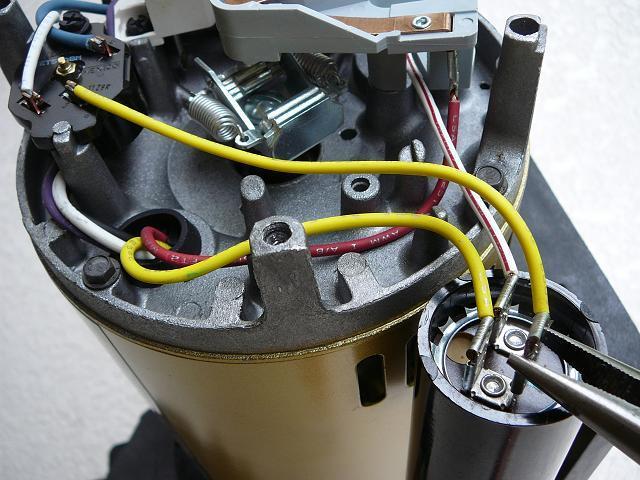
The location of the pool pump capacitor is indicated in this diagram. We have already discussed the two types of capacitors in a pool pump: the Start capacitor and the run capacitor.
The capacitor enables the pool pump to reach operating speed before switching to a new power source. And, of the two capacitors, the run capacitor has a longer lifespan than the start capacitor.
How Do You Wire a Pool Pump Capacitor?
There are basically two terminals in a capacitor. And two wires are connected to these two terminals. Which wire will enter which terminal that is not fixed. Because the polarity in a capacitor is not a major concern.
There might have up to four terminals in a capacitor. But in such a scenario, a pair of terminals is the same and the other pair is the same. While wiring we can use any of the terminals among the two terminals from a pair.
A pool pump capacitor is typically 20 microfarad in size. It might be as little as 40 micro Farad. When changing a pool pump capacitor, the most important thing to remember is that the new capacitor must be the same size as the old one.
Before we wire a pool pump capacitor, we must make sure there is no charge in the capacitor. Otherwise, the user’s safety may be risked.
Wire Routing Path on a Capacitor
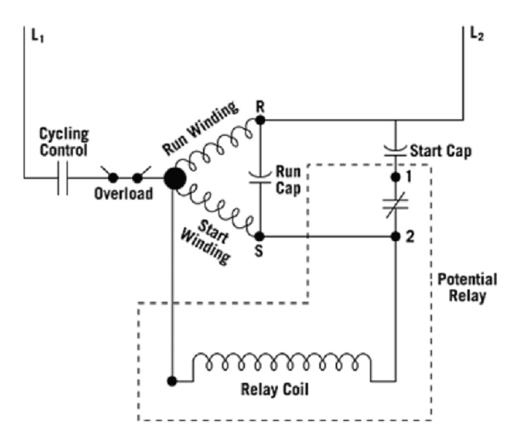
The common terminal on the load side of the unit’s contactor to the wire terminal on the start capacitor relay’s “Common” wire, commonly the black wire. This contactor terminal is linked to the wires attached to the motor’s common terminal, which is labeled “C” or “COM” on the wiring diagram.
The “Run” wire from the start-capacitor relay onto the “HERM” terminal on the run capacitor This run capacitor connection is linked to the wire attached to the motor’s start terminal, which is labeled “S” on the wiring diagram.
How Do You Check if The Pool Pump Capacitor Is Bad or Not?
First, inspect the pool pump’s components. Before starting the diagnostics, turn off all electricity and turn off all breakers. Start by inspecting the impeller and motor shaft to verify whether they are freely spinning. This will rule out corrosion between the rotor and stator, as well as something heavy lodged in the impeller.
Assess the capacitor’s look next. You can presume it’s failed if it’s bulged, fractured, or otherwise appears damaged. Check the capacitor for any loose, crimped, or broken wires, rusted terminals, or burnt markings.
What Are the Reasons for the Failure of a Pool Pump Capacitor?
- Failure will occur if a capacitor is replaced with the wrong one. For example, in order to replace a faulty 20 microfarad capacitor, we must utilize a 20 microfarad capacitor. Failure will occur if we utilize a 40 microfarad capacitor.
- When a motor runs lightly loaded or heated, it might result in excessive capacitor voltage, which can lead to failure. Due to constraints, such as an air leak, light-loading or running hot might occur.
- The capacitor is defective from the start, either because it came from a substandard batch or because it was mistreated before installation.
Can You Run a Pump Without a Capacitor
Without the capacitor, the motor will run perfectly. The issue arises when the motor stops and tries to restart. Let’s say you get a power glitch that lasts a second or two. The pump will shut down and will not be able to restart, causing the motor to fail.
Does a pool pump capacitor have polarity?
There is no concern about the polarity of the pool pump capacitor because it is a VAC capacitor.
Conclusion
In the motor of the pool pump, there are two capacitors in total. The start capacitor and the run capacitor are two different capacitors. The pool pump capacitor’s job is to provide enough energy for your pump’s motor to reach critical velocity (or RPM) before switching to another power source.
Subscribe to our newsletter
& plug into
the world of circuits