Power Riser Diagram | How Electricity Enters the Facility?
A power riser diagram depicts the vertical distribution of electrical power within a building. It shows how electricity enters the facility and is stepped down and distributed to various floors and loads.
Understanding power riser diagrams is critical for electrical engineers, technicians, and facilities managers. This article will give an overview of the Power Riser Diagram.
What is a Power Riser Diagram?
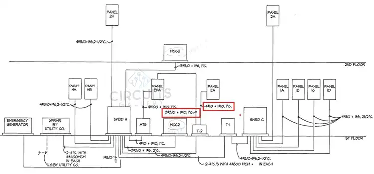
A power riser diagram is a schematic diagram that shows the distribution of electrical power on various levels throughout a building via switchboards, panelboards, and other distribution equipment.
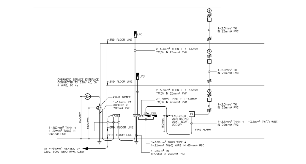
Fig. Power Riser Diagram.
The main purposes are:
- Visualize the full distribution hierarchy from utility feed to branch circuits
- Ensure proper distribution-equipment sizes and locations
- Coordinate electrical rooms and conduit routing between floors
- Balance electrical loads across phases
- Meet code separation requirements between key components
- Provide a reference for maintenance troubleshooting and future changes
Without a riser diagram, it is extremely difficult to fully grasp the complex electrical system layout of a large facility.
Standards and Requirements for Power Riser
Power riser diagrams must adhere to several key standards:
NFPA 70: National Electrical Code (NEC): This outlines specific electrical installation requirements for safety. Important aspects include wire and conduit sizing, overcurrent protection, grounding, and more.
NFPA 101: Life Safety Code: This establishes requirements to maximize safety from fire and electrical hazards.
IBC, IFC: Adopted building codes impact electrical rooms, system protection, and seismic bracing.
UL, ANSI, NEMA: Equipment must meet safety and testing standards from these organizations.
Project specifications: The customer usually defines technical specifications that the electrical design and equipment selections must satisfy.
Major Components of Power Riser Diagram
The major components of a power riser diagram include:
Service Entrance
The service entrance is the location where external power enters the building’s electrical system. This includes:
Service transformers: Used to step down power company distribution voltages to utilization levels like 480V 3-phase.
Main switchboard (MSB): The central hub where power first enters. Contains a main breaker, metering, and surge protection.
Emergency power: If equipped, generators and transfer switches provide backup power in case of utility outages.
Main feeder capacity: The size and capacity of main conductors are noted in amps.
Vertical Distribution
The MSB distributes power up through floors via feeders and switchboards:
Feeders: Large-ampacity feeder circuits serve switchboards on upper levels. Feeder size and count are noted.
Vertical bus or wireways: Protect and route feeders passing through multiple floors.
Intermediate switchboards: Provides distribution points on each floor to supply power to downstream panelboards.
Panelboards: Supply power to branch circuits serving lights, receptacles, and other loads on each floor.
Step-down transformers: Convert high distribution voltages like 480V to 120/208V for lighting and receptacle panels.
Electrical Rooms
Electrical rooms and closets provide space for distribution equipment:
Main distribution room: Houses main switchboard lineups and service entrance equipment.
Electrical closets: Smaller rooms on upper floors for floor-level switchboards and panelboards.
Equipment rooms: Larger spaces for big loads like HVAC equipment. May contain transformers and motor controls.
Additional Components
Surge protection devices (SPDs): Protect equipment from voltage surges at service entrances or distribution points.
Meters: Monitor electrical consumption for tenant billing purposes and diagnostics.
Grounding: Bond all equipment together and tie it to a grounding electrode system.
Reading and Interpreting Diagrams
With practice, electrical engineers and technicians can learn to interpret power riser diagrams by understanding:
Orientation: Power flows from bottom to top starting with the main service entrance on the bottom.
Layout: Power flows from left to right through levels of distribution components.
Symbols: Recognizing standard symbols for transformers, breakers, meters, etc. is crucial.
Labels: Equipment tags identify location and electrical characteristics like voltage, phases, and hierarchy.
Connections: Pay attention to bus taps and conduits showing how power flows between equipment.
Scaling: Components are exaggerated in size to fit the page, not 1:1 scale.
Dimensions: Key ratings for volts, amps, and capacity are noted for each component.
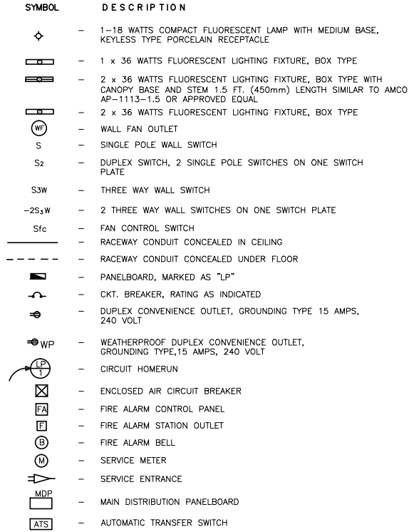
Fig. Symbols in Power Riser Diagram.
Frequently Asked Questions (FAQs)
What Is the Typical Scale Used for Power Riser Diagrams?
Answer: Power riser diagrams are usually drawn at a smaller scale like 1/4″ = 1′-0″ or 1/8″ = 1′-0″. This allows the full height of the building to be shown on a standard page size.
How Are Junction Boxes and Pull Points Identified?
Answer: Small dots along distribution lines indicate handy box and pull point locations for installers to transition wiring between floors and components.
What Phase Configuration Is Typically Used?
Answer: Most buildings use 3-phase 120/208V or 277/480V power. Larger facilities may use medium voltage distribution at >600V.
To Conclude
A power riser diagram is vital for electrical engineers to design safe, reliable systems that meet city codes and customer needs. Understanding how to read power riser diagrams allows technicians to troubleshoot problems faster.
Subscribe to our newsletter
& plug into
the world of circuits