Skip to content
Circuits Gallery
  • Home
  • BasicsExpand
    • Wiring
    • Op-Amp
    • Circuitry
    • Oscilloscope
    • Conductivity
    • Components
  • MicroControllerExpand
    • Arduino
    • PIC
    • Simulation
  • ProjectExpand
    • Using 555 Timer
  • DigitalExpand
    • Communication
  • Submit Project
Circuits Gallery
Home / Digital / Communication / Pulse Width Demodulation Theory With Block Diagram and Waveform | The Basics Explained

Pulse Width Demodulation Theory With Block Diagram and Waveform | The Basics Explained

PWM pulse can be detected using a Ramp generator and some circuit combinations. But how to detect or demodulate a Pulse Width Modulated Signal? The block diagram itself explains all the decoding principles. Waveforms at different sections of Pulse width demodulation are also given here.

We have discussed the PWM generator circuit using 741 op-amps in previous articles. The coded message in the form of PWM can be easily decoded with the help of a synchronous pulse. The most simple demodulation principle of PWM signals is described in this article

Block Diagram of PWM Demodulator

Block Diagram of PWM Demodulator
Block Diagram of a PWM Demodulator
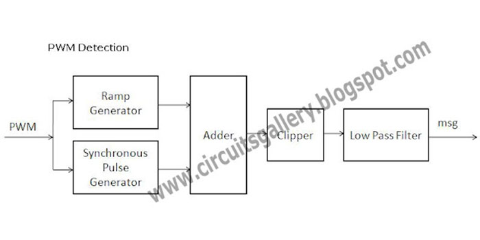
  • PWM coding can be done using the 741 op-amps that we discussed before. Here the modulated (PWM) wave is applied to the decoder system for getting the message signal.
  • The basic theory behind Pulse width demodulation is converting the PWM signal to PAM (Pulse Amplitude Modulation) signal. PAM can be easily detected by a suitable low pass filter.
Block Diagram of PWM Demodulator
  • Input PWM wave is applied to Ramp generator and Synchronous Pulse generator (see the block diagram).
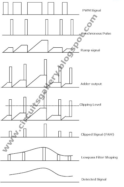
  • One synchronous pulse generator will generate a pulse waveform such that the pulse will end at the beginning of each PWM pulse (See the fig below)
  • The ramp generator will produce a ramp signal whose amplitude is proportional to the width of the PWM signal (See the fig below)
  • Now apply these Ramp and Synchronous pulses to an Adder circuit which adds these signals together.
  • The next block is a positive Clipper with a specific voltage; Clipper clips the waveform at a particular level as shown in fig.
  • The output of the clipper will be the PAM signal, now the PWM signal gets converted to the PAM signal.
  • The PAM can be demodulated by the Low Pass filtering method. Thus our next block is Low Pass Filter.

Ramp Generator + Synchronous Pulse + Adder + Clipper = PWM to PAM Converter

Conclusion

Each and every step of PWM demodulation waveforms are shown in the chart we made. PWM signals have wide verities of applications like PWM Inverter circuit, PWM LED brightness control or Dimmer circuit, etc.

Table Of Contents
  1. Block Diagram of PWM Demodulator
  2. Conclusion

Subscribe to our newsletter

& plug into

the world of circuits

    A seasoned electronics enthusiast, Charles Clark is a key contributor to Circuits Gallery. From basic components to advanced microcontroller projects, Charles simplifies complex concepts with ease. His writings are a blend of expertise and passion, making electronics accessible to all. Whether it's circuitry or digital communication, Charles is the voice you can trust.

    Facebook Twitter Instagram

    Recent Blogs

    • How to Make A 75 To 300 Ohm Matching Transformer
      How to Make A 75 To 300 Ohm Matching Transformer? | A Step by Step Guide for You
    • How to Download Circuit Wizard? | Procedure for Downloading the Latest Version
    • What Gauge Wire from Battery to Starter
      What Gauge Wire from Battery to Starter? | Choosing the Right Wire Gauge
    • What Does 50 Milliamps Look Like on a Multimeter
      What Does 50 Milliamps Look Like on a Multimeter? | Let’s Find Out
    • How Many Watts Does a 32 Inch TV Use
      How Many Watts Does a 32 Inch TV Use? | Find Out the Required Wattage for Different Brands
    • What Size Conduit for 122 Wire
      What Size Conduit for 12/2 Wire? | Choosing the Right Conduit for Your 12/2 Wire

    Browse Categories

    • Arduino
    • Basics
    • Circuitry
    • Communication
    • Components
    • Conductivity
    • Digital
    • How To
    • MicroController
    • Op-Amp
    • Oscilloscope
    • PIC
    • Project
    • Simulation
    • Using 555 Timer
    • Wiring
    Circuits Gallery
    Join Our Community:

    Quick Links

    • About Us
    • Privacy Policy
    • Terms and Conditions
    • Submit Your Project
    • Contact Us

    Our Story

    Our journey designing innovative devices had immersed us in convoluted electronics. We realized mastery doesn't require elite degrees or industry secrets—just knowledge presented coherently. We became devoted to unraveling even quantum-complex circuits, diagram by diagram, so anyone eager to learn can unlock these secrets. By simplifying electronics fundamentals, we hope to ignite innovation in generations to come.

    © Copyright 2025 Circuits Gallery | All Rights Reserved.

    • Home
    • Basics
      • Wiring
      • Op-Amp
      • Circuitry
      • Oscilloscope
      • Conductivity
      • Components
    • MicroController
      • Arduino
      • PIC
      • Simulation
    • Project
      • Using 555 Timer
    • Digital
      • Communication
    • Submit Project
    Search