Push Start Button Diagram | Guidelines
The push start button system consists of key components: the key fob for wireless access, the start/stop button as the ignition trigger, an antenna ring/receiver for signal detection, and the Engine Control Module (ECM) managing crucial functions.
The wiring diagram visually outlines the connections among these components for a seamless push-button start experience. The technical breakdown emphasizes key steps: key fob authentication, authorization via the ECM, button activation, and the subsequent engine ignition process. We will now expand our idea on the diagram.
Components of a Push Start Button System
The push start button system comprises of a few key components. And the wiring diagram later will illustrate the connections among these components for a seamless push-button start experience.
1. Key Fob
This handheld device serves as the electronic key to the vehicle. It communicates wirelessly with the car’s computer system, allowing access and authorization for engine startup.
2. Start/Stop Button
The centerpiece of the system, this button triggers the ignition process. It typically illuminates when the vehicle’s electrical system is active, prompting the driver to press it when starting or turning off the engine.
3. Antenna Ring/Receiver
Positioned near the button, this component detects the key fob’s signal when it’s within range. It establishes a secure connection between the fob and the vehicle’s computer system.
4. Engine Control Module (ECM)
The brain of the vehicle’s electronic system, the ECM manages various functions, including ignition timing, fuel injection, and more. It processes the signal from the key fob and authorizes the engine to start when a valid signal is received.
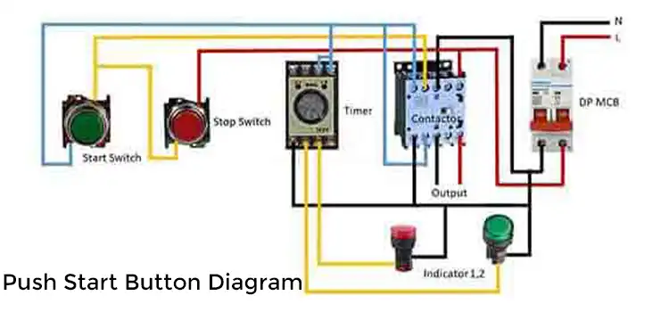
Wiring Diagram of Push Start Button
Image 1- Wiring Diagram of Push Start Button
Dissecting the Technical Anatomy of the Push Start Button System
The push-start button diagram illustrates the flow of signals and interactions among these components, showcasing the sequence of events that lead to engine activation. Here’s a simplified breakdown:
1. Key Fob Authentication
When the driver approaches the vehicle with the key fob, the antenna ring detects its signal. The receiver authenticates the key fob’s identity by exchanging encrypted signals.
2. Authorization Process
Upon successful authentication, the receiver sends a signal to the ECM, verifying the key fob’s legitimacy. If the key fob is recognized and authorized, the ECM allows the ignition process to proceed.
3. Button Activation
With the authorized key fob in range, the driver presses the start/stop button. This action sends a signal to the ECM, prompting it to initiate the engine startup sequence.
4. Engine Ignition
The ECM triggers the necessary systems, including fuel delivery and ignition timing, to start the engine. Once the engine is running, the ECM monitors its performance and adjusts various parameters for optimal operation.
Frequently Asked Questions
How does a push-start button diagram differ from a traditional ignition system diagram?
In a push-start button diagram, the system relies on an electronic signal from the key fob to initiate the starting sequence, whereas a traditional ignition system diagram involves a mechanical key turning in the ignition cylinder to start the engine.
What do the different symbols and lines represent in a push-start button diagram?
Symbols in the diagram represent various components such as the push start button, key fob, battery, relays, wires, and connections. Lines depict the electrical pathways or connections between these components.
Conclusion
The push-start button diagram encapsulates the intricate interplay between electronic components, key fob authentication, and the vehicle’s computer system. This modern ignition system streamlines the startup process while enhancing security and convenience for drivers.
Subscribe to our newsletter
& plug into
the world of circuits